Separate steel grid shear wall based on T-shaped steel members

A technology of T-shaped steel and shear walls, which is applied in the direction of building components, walls, and building structures, can solve the problems of reducing lateral bearing capacity, deformation of thin steel plates outside the surface, and increasing the force burden of steel plate walls, so as to ensure accurate and high efficiency, reduced calculation difficulty and time-consuming, convenient transportation and on-site installation

Pending Publication Date: 2018-08-17
TIANJIN UNIV RES INST OF ARCHITECTRUAL DESIGN & URBAN PLANNING +1
View PDF7 Cites 2 Cited by
  • Summary
  • Abstract
  • Description
  • Claims
  • Application Information

AI Technical Summary

Problems solved by technology

[0004] Currently commonly used steel plate shear walls are generally divided into thick steel plate walls with non-stiffening ribs, steel plate walls with stiffening ribs, thin plate walls with non-stiffening ribs, steel plate walls with slots on both sides, and profiled steel plate walls. There are still some problems in the application, such as the large amount of steel used for thick steel plates; thin steel plates are prone to out-of-plane deformation and there are residual stresses and defects in the welds; stiffeners are prone to local buckling; the relevant calculation formulas in the code are relatively complicated; On-site installation is more difficult and other technical problems
In addition, in the current design process of the steel plate shear wall, if the steel plate wall is allowed to be installed together with the main structure, the steel plate wall will bear more vertical load due to its high vertical stiffness, thereby increasing the force burden of the steel plate wall, to a certain extent reduce its lateral bearing capacity; if the steel plate wall is required to be installed after the main structure is capped so as not to bear large vertical loads, it will affect the construction speed on site

Method used


Image

  • Separate steel grid shear wall based on T-shaped steel members
  • Separate steel grid shear wall based on T-shaped steel members
  • Separate steel grid shear wall based on T-shaped steel members

Examples


Embodiment Construction

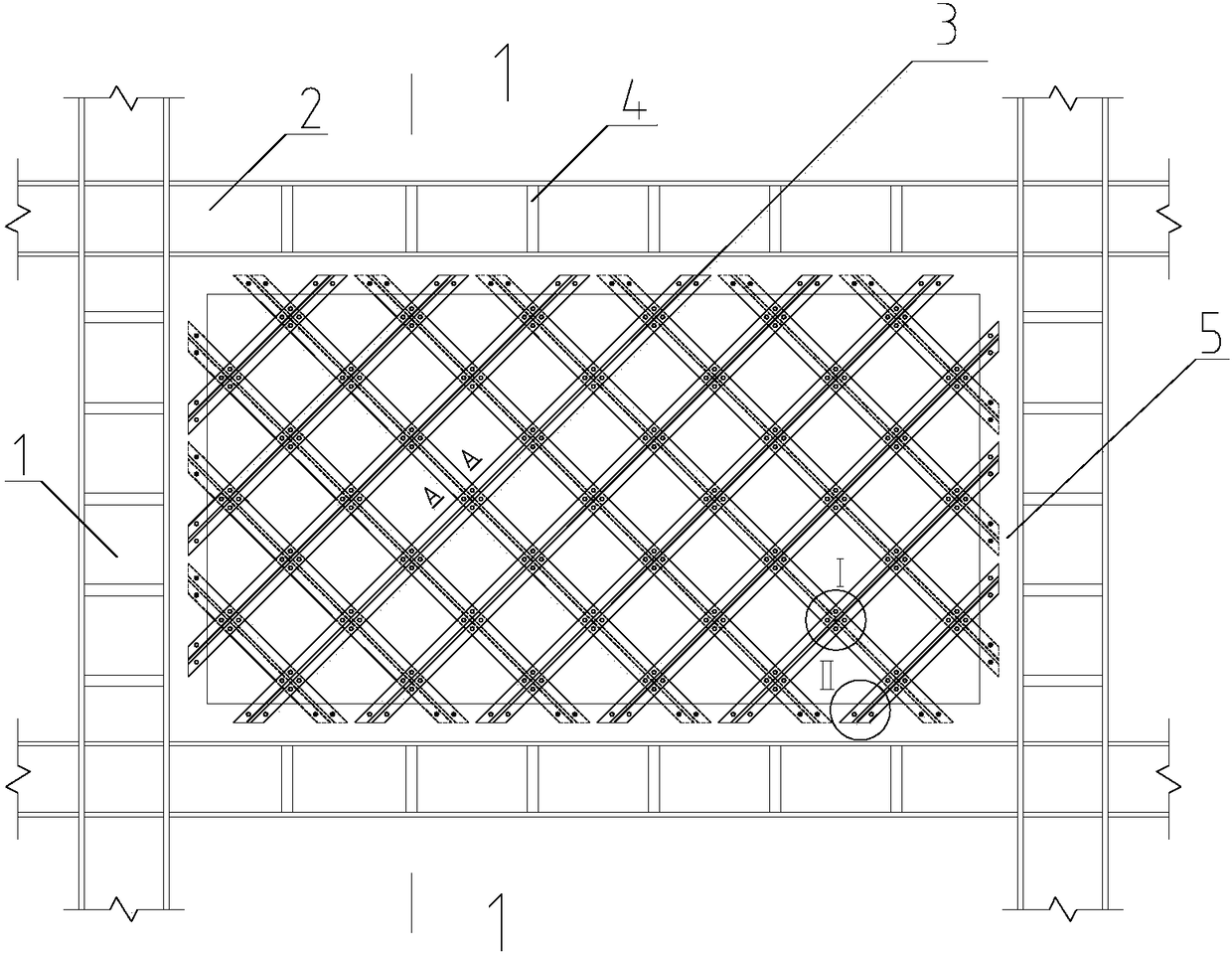
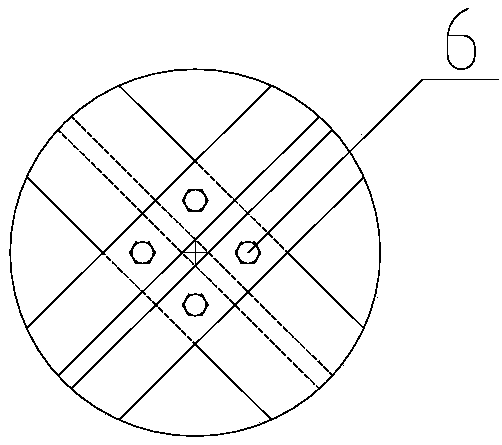
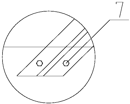
[0027] In order to further understand the invention content, characteristics and effects of the present invention, the following examples are given, and detailed descriptions are as follows in conjunction with the accompanying drawings:

[0028] see Figure 1 to Figure 5 , a separated steel grid shear wall based on T-shaped steel members, the basic idea is to discretize the embedded steel plates into T-shaped steel members 3 arranged in two-way separation, and the T-shaped steel members 3 are mixed according to the existing steel plate shear wall The basic principle of the bar system simplified calculation model is set, the T-shaped steel member 3 is provided with a flange plate 3-1 and a web 3-2, the flange plate 3-1 is equivalent to a steel plate wall, and its web 3-2 is equivalent to Stiffeners.

[0029] In this embodiment, the shear wall adopts a grid structure. More specifically, the grid structure is formed by connecting a plurality of T-shaped steel members 3 arranged...


PUM


Abstract

The invention discloses a separate steel grid shear wall based on T-shaped steel members. An embedded steel plate is discretely arranged into the bi-directionally separated T-shaped steel members, andthe T-shaped steel members are arranged according to a basic principle of an existing steel plate shear wall mixed rod system simplification and calculation model. On the basis of the mixed rod system model, the embedded steel plate is of a steel grid structure composed of the T-shaped steel members, and the problems of large steel consumption of a steel plate shear wall system, deformation of outer surfaces of steel plates, residual stress, difficulty in construction and installation on site and the like can be solved. By reducing the vertical stiffness, the problem that steel plate shear walls bear large vertical loads when installed together with main body members can be solved. Therefore, the purposes of saving materials, simplifying model analysis, increasing the industrialization level, accelerating the construction and developing fabricated steel structure buildings are achieved.

Description

technical field [0001] The invention relates to a steel plate shear wall, in particular to a separated steel grid shear wall based on T-shaped steel components. Background technique [0002] The steel plate shear wall is a new type of lateral force resistant structural system suitable for high-rise and super high-rise buildings in high-intensity areas. Under the action of strong earthquakes, the deformation of the steel plate shear wall is a typical nonlinear problem of two-dimensional plate elements. However, due to the difficulty and time-consuming calculation of the two-dimensional nonlinear fine model of the wall plate, it is necessary to satisfy the structural calculation requirements. Under the premise of safety and accuracy, it is necessary to adopt a reasonable simplified analysis model. [0003] Since the simplified analysis model of steel plate shear wall was proposed in the 1980s, relevant experts have been continuously researching and improving it, and have succ...

Claims


Application Information

Patent Timeline
Patent Type & Authority Applications(China)
IPC IPC(8): E04B2/56E04B2/60
CPCE04B2/56E04B2/60
Inventor 闫翔宇段岩陈志华于敬海周婷王丹妮张希
Owner TIANJIN UNIV RES INST OF ARCHITECTRUAL DESIGN & URBAN PLANNING
Why Eureka
Try Eureka