Anaerobic reactor and organic printing-dyeing wastewater treatment system comprising same

An anaerobic reactor and treatment system technology, applied in the field of organic printing and dyeing wastewater treatment systems, can solve the problems of low decolorization efficiency, large amount of sludge carried out, poor treatment effect, etc., achieve good treatment effect, low input cost, The effect of improving processing performance

Pending Publication Date: 2018-08-17
JIANGSU INST OF URBAN PLANNING & DESIGN
View PDF9 Cites 0 Cited by
  • Summary
  • Abstract
  • Description
  • Claims
  • Application Information

AI Technical Summary

Problems solved by technology

[0006] The purpose of the present invention is to provide an anaerobic reactor and an organic printing and dyeing wastewater treatment system containing the reactor in view of the shortcomings of the printing and dyeing wastewater treatment method in the prior art, such as low decolorization efficiency, large amount of sludge carried out, and poor treatment effect. The equipment structure is simple, the input cost is low, the operation is convenient, and the treatment effect is good.

Method used


Image

  • Anaerobic reactor and organic printing-dyeing wastewater treatment system comprising same
  • Anaerobic reactor and organic printing-dyeing wastewater treatment system comprising same
  • Anaerobic reactor and organic printing-dyeing wastewater treatment system comprising same

Examples


Embodiment 1

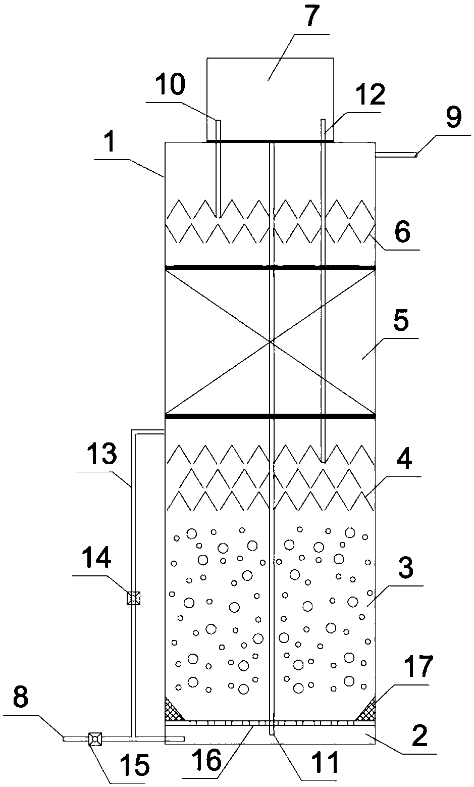
[0035] Embodiment 1: as figure 1 As shown, an anaerobic reactor includes a tower body 1, and the inside of the tower body 1 is sequentially provided with a water distribution area 2, a high-load anaerobic treatment area 3, a first-stage three-phase separation area, an anaerobic biological Membrane treatment zone 5, secondary three-phase separation zone and gas-water separation zone 7.

[0036] The water distribution area 2 is arranged at the bottom of the tower body 1 and includes a water inlet pipe 8 , a water inlet pump 15 and a water distributor 16 . The water inlet pipe 8 is connected to the water inlet at the bottom of the tower body 1; the water inlet pump 15 is arranged on the water inlet pipe 8; the water distributor 16 is arranged on the upper part of the water distribution area 2; The water dispenser 16 is a flat plate with uniform hole distribution, and the diameter of the circular hole is 10-50mm; the connection part between the water dispenser 16 and the tower bo...

Embodiment 2

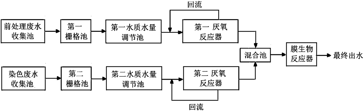
[0042] Embodiment 2: as figure 2 As shown, a high-concentration organic printing and dyeing wastewater treatment system includes a pretreatment wastewater treatment system, a dyeing wastewater treatment system and a membrane bioreactor; the pretreatment wastewater treatment system and the dyeing wastewater treatment system are respectively connected with the membrane The bioreactor is connected; the pre-treatment wastewater treatment system includes a pre-treatment wastewater collection tank, the first grid tank, the first water quality and quantity adjustment tank and the first anaerobic reactor connected in sequence; the dyeing wastewater treatment system includes sequentially The connected dyeing wastewater collection pond, the second grid pond, the second water quality and quantity regulating pond and the second anaerobic reactor;

[0043] The first anaerobic reactor and the second anaerobic reactor are respectively connected with a mixing tank, and the mixing tank is con...


PUM

PropertyMeasurementUnit
particle diameteraaaaaaaaaa

Abstract

The invention discloses an anaerobic reactor and an organic printing-dyeing wastewater treatment system comprising the same. The anaerobic reactor comprises a tower, a water distribution area, a high-load anaerobic treatment area, a primary triphase separation area, an anaerobic bio-membrane treatment area, a secondary triphase separation area and a gas-water separation area are sequentially arranged inside the tower from bottom to top. The anaerobic reactor is simple in structure, low in input cost, convenient to operate, capable of respectively collecting and treating according to water quality difference of wastewater generated by different processes, highly targeted, excellent in treatment effect and capable of finally making outgoing water to meet discharging standard requirements.

Description

technical field [0001] The invention belongs to the technical field of water treatment equipment, and in particular relates to an anaerobic reactor and an organic printing and dyeing wastewater treatment system containing the reactor. Background technique [0002] Printing and dyeing enterprises are one of the major pollutant dischargers in various industries of the national economy, and their annual discharge ranks among the top five in the wastewater discharge of various industrial enterprises in the country, and there is a trend of increasing year by year. Printing and dyeing wastewater is mainly composed of desizing wastewater, boiling wastewater, bleaching wastewater, mercerizing wastewater, dyeing wastewater, auxiliaries, slurry, acid and alkali, etc. It has the characteristics of high concentration, deep color, complex components, and poor biochemical properties. If it is directly discharged without treatment, it will cause water pollution and may directly or indirect...

Claims


Application Information

Patent Timeline
Patent Type & Authority Applications(China)
IPC IPC(8): C02F3/28C02F9/14C02F103/30C02F101/16C02F101/38
CPCC02F3/282C02F2103/30C02F2101/16C02F2101/38C02F3/00C02F1/001
Inventor 林俊雄朱建国曹万春江心孔赟
Owner JIANGSU INST OF URBAN PLANNING & DESIGN
Why Eureka
Try Eureka