
Super-resolution telescope imaging method and system

An imaging method and super-resolution technology, applied in optical components, instruments, optics, etc., can solve problems such as limited application range, difficulty in obtaining prior information, and difficulty in additional constraints, so as to improve spatial resolution and break through the diffraction limit Effect

Active Publication Date: 2020-09-22
NANJING INST OF ASTRONOMICAL OPTICS & TECH NAT ASTRONOMICAL OBSE
View PDF3 Cites 0 Cited by
  • Summary
  • Abstract
  • Description
  • Claims
  • Application Information

AI Technical Summary

Problems solved by technology

However, in astronomical telescopic observations, prior information about the observed objects is usually difficult to obtain, making it difficult to introduce additional constraints
At present, the application range of super-resolution image reconstruction technology in astronomical images is still very limited

Method used


Image

  • Super-resolution telescope imaging method and system
  • Super-resolution telescope imaging method and system
  • Super-resolution telescope imaging method and system

Examples


Embodiment 1

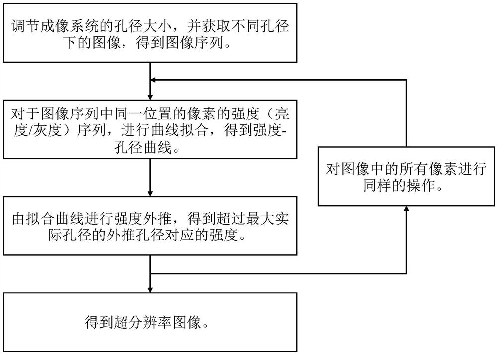
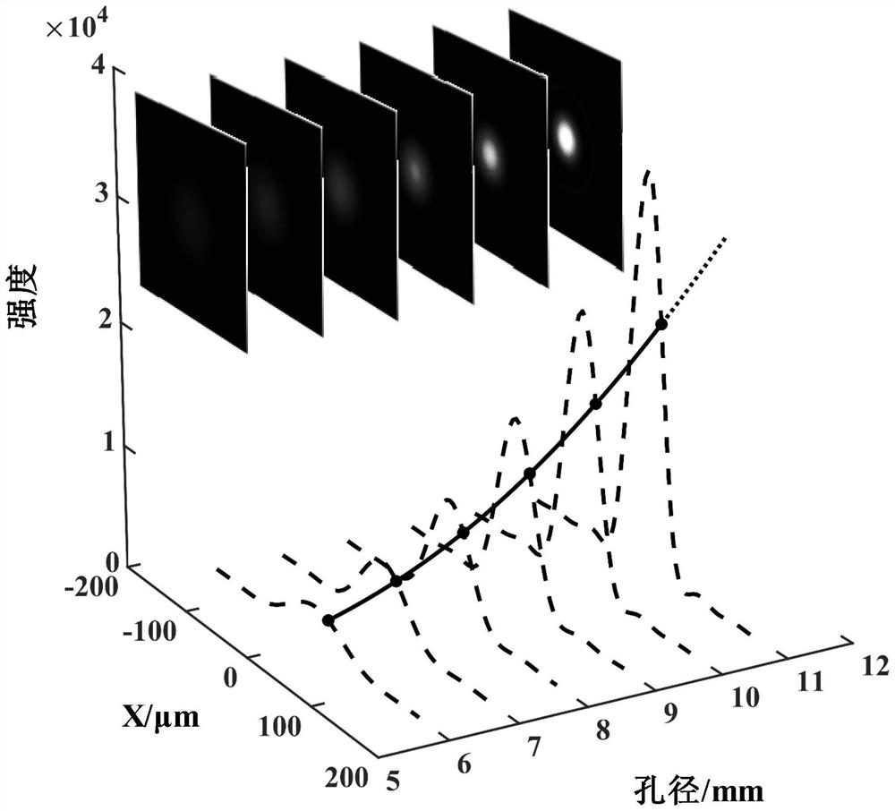
[0026] Embodiment 1, super-resolution telescope imaging method and system thereof, with reference to the accompanying drawings: figure 1 It is a block diagram of the technical scheme of the super-resolution telescope imaging method proposed by the present invention. The basic idea of ​​this method is that since the intensity distribution on the image plane changes continuously with the change of the aperture, the intensity corresponding to the aperture beyond the maximum actual aperture can be obtained by curve fitting and extrapolation. figure 2 Taking a single point light source as an example, a schematic diagram of the aperture modulation and intensity extrapolation of the proposed super-resolution method is shown. The six inserted images are the images formed by a single point light source through a diffraction-limited system with different apertures, which can be expressed by the following formula:

[0027]

[0028] in,

[0029]

[0030] I 0 is the maximum inten...


PUM


Abstract

A super-resolution imaging method and a system thereof are disclosed. The method comprises the following steps S1 an aperture size of an imaging system is adjusted; S2 corresponding images under different apertures are collected, and an image sequence is obtained; S3 a series of intensity-aperture data for pixels at a location in the image sequence is subjected to curve fitting operation, and a fitted intensity-aperture curve is obtained; S4 according to the obtained fitted curve, an intensity corresponding to an extrapolated aperture exceeding an actual maximum aperture of the imaging systemis extrapolated; S5 all pixels in the image sequence are extrapolated to an intensity of the same extrapolated aperture in accordance with steps S3 and S4; S6 all obtained extrapolated intensities form an image according to original pixel positions. Via the method and the system disclosed in the invention, details that cannot be distinguished originally can now be distinguished, a diffraction limit is broken, and a spatial resolution can be improved. Artificial radiation illumination on an object being observed is not needed, and prior information of the object being observed is also not needed.

Description

technical field [0001] The invention relates to the imaging field, in particular to a super-resolution telescope imaging method. The invention also relates to a device system used in the super-resolution telescope imaging method. Background technique [0002] The optical telescope imaging system is a very important long-distance observation and imaging device, especially in the field of astronomy. In practical applications, people hope to obtain images with very high spatial resolution (spatial resolution) through the telescope imaging system, so as to obtain more detailed information about the observed objects. However, the spatial resolution of the telescope imaging system is limited by the diffraction limit, so that the spatial resolution of a telescope imaging system with an aperture of D is limited to 1.22λf / D (λ is the wavelength of the incident light wave, f is the imaging focal length of the system). In order to obtain higher spatial resolution, people have built ...

Claims


Application Information

Patent Timeline
Patent Type & Authority Patents(China)
IPC IPC(8): G02B27/58
CPCG02B27/58
Inventor 徐彪何晋平
Owner NANJING INST OF ASTRONOMICAL OPTICS & TECH NAT ASTRONOMICAL OBSE
Learn More