
A sintering process homogeneity detection system and method

A sintering process and detection system technology, applied in the sintering field, can solve problems such as sinter quality fluctuations, high ore return volume, instability, etc., to achieve the effect of solving horizontal and vertical unevenness, improving quality and output, and avoiding over-burning

Active Publication Date: 2019-06-28
ANGANG STEEL CO LTD
View PDF4 Cites 0 Cited by
  • Summary
  • Abstract
  • Description
  • Claims
  • Application Information

AI Technical Summary

Problems solved by technology

[0009] The purpose of the present invention is to provide a detection system and method for the uniformity index of the sintering process, so as to realize the quantitative analysis of the uniform state of the mixture bed, and solve the fluctuation of the sinter quality caused by the horizontal and vertical unevenness in the sintering process, and the amount of returned ore high and unstable problems

Method used


Image

  • A sintering process homogeneity detection system and method
  • A sintering process homogeneity detection system and method
  • A sintering process homogeneity detection system and method

Examples


Embodiment 1

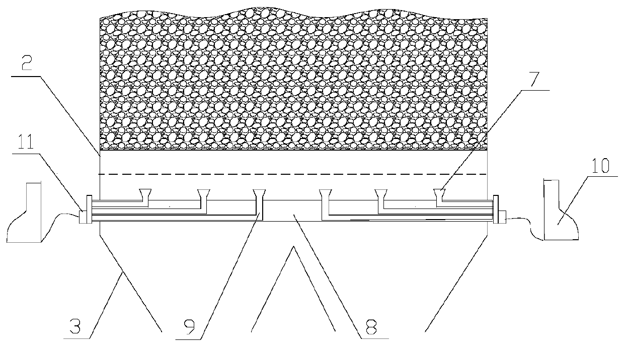
[0034] The protection sleeve 8 has 4 sleeve holes on the side facing the sintered material layer; the front ends of the 4 sampling tubes 9 are penetrated by the opening end of the protection sleeve 8, and respectively pass through the sleeve holes. The area of ​​the upper mouth of the sampling cup is 10mm 2 . The two flue gas sampling devices 4 are respectively installed on the two adjacent bellows 3 just outside the igniter 1 of the machine head, which is called the first sampling group; the two flue gas sampling devices 4 are respectively installed on the penultimate third and On the second bellows 3, it is called the second sampling group. In the first sampling group and the second sampling group, the area at the bottom of the sintering trolley 2 where each sampling tube 9 of the flue gas sampling device 4 is located corresponds to the ignition area of ​​each igniter burner 6 and the control of each cloth auxiliary door 5 respectively. Cutting area.

[0035] The specific...

Embodiment 2

[0047] The protective casing 8 has 6 casing holes; the front ends of the 6 sampling tubes 9 are penetrated through the opening end of the protective casing 8, and then passed through the casing holes respectively. The area of ​​the upper opening of the sampling cup 7 is 3dm2. 3 pieces The flue gas sampling devices 4 are respectively installed on the three adjacent bellows 3 just outside the igniter 1 of the machine head, which is called the first sampling group; the three flue gas sampling devices 4 are respectively installed at the fourth and third from the bottom of the machine tail. and the second bellows 3, called the second sampling group. In the first sampling group and the second sampling group, the area at the bottom of the sintering trolley 2 where each sampling tube 9 of the flue gas sampling device 4 is located corresponds to the ignition area of ​​each igniter burner 6 and the control of each cloth auxiliary door 5 respectively. Cutting area. The flue gas analyzer...


PUM


Abstract

The invention discloses a homogeneity detection system and method for a sintering process. The homogeneity detection system comprises flue gas sampling devices, a flue gas analyzer and a flue gas control device, each flue gas sampling device is composed of a protective sleeve, a flue gas sampling tube and a sampling cup, and the flue gas control device is composed of a data processing unit and a control adjusting unit. Flue gas sampling is conducted on an ignition area of each igniter burner corresponding to the bottom area of a sintering trolley where the sampling tubes are located and a discharging area controlled by each material distributing auxiliary door by the sampling tubes; and the flue gas control device calculates the effective air rate of the area corresponding to each samplingtube according to the flue gas composition, the effective air rates of the areas corresponding to the different sampling tubes in the same flue gas sampling device and the effective air rates of theareas corresponding to the different sampling tubes of the adjacent bellows flue gas sampling devices are analyzed and compared, and the igniter burner and the material distributing auxiliary door ofa corresponding area are adjusted correspondingly according to the situation that whether the effective air rates are consistent within an error range or not. According to the homogeneity detection system and method for the sintering process, quantitative analysis of the uniform state of a sintering mixing material bed is achieved, the sintering quality and yield are improved, over burning is avoided, and abrasion of a fire bar of the trolley is lightened.

Description

technical field [0001] The invention belongs to the technical field of sintering, in particular to a system and method for detecting the homogeneity of a sintering process. Background technique [0002] In iron and steel production, iron ore needs to be processed by a sintering system before being smelted in a blast furnace, that is, a variety of powdery iron-containing raw materials are mixed with an appropriate amount of fuel and flux, and an appropriate amount of water is added. After mixing and pelletizing, the cloth is Put it on the sintering trolley and roast it to cause a series of physical and chemical changes to form sintered ore that is easy to smelt. This process is called sintering. [0003] In the sintering process, there are many factors affecting the output and quality of sintering ore, the main factors can be summarized as fluctuations in chemical composition and improper control of the sintering end point. Under a certain raw material structure, in order to...

Claims


Application Information

Patent Timeline
Patent Type & Authority Patents(China)
IPC IPC(8): F27B21/14
CPCF27B21/00F27D19/00F27D2019/0006F27M2003/04
Inventor 张辉周明顺宫作岩翟立委刘杰徐礼兵刘帅彭彬孙雷
Owner ANGANG STEEL CO LTD
Learn More