
Annular air inlet atomizing humidifier

A technology of humidifier and circular air duct, which is applied in the direction of air humidification system, heating method, lighting and heating equipment, etc. It can solve the problems of low atomization efficiency and achieve the effects of single path, high utilization rate and improved atomization efficiency

Pending Publication Date: 2018-08-14
SHENZHEN QIANHAI PATUOXUN NETWORK & TECH CO LTD
View PDF5 Cites 0 Cited by
  • Summary
  • Abstract
  • Description
  • Claims
  • Application Information

AI Technical Summary

Problems solved by technology

[0003] Aiming at the problem of low atomization efficiency of the current humidification products mentioned above, the present invention provides an atomizing humidifier with an annular air inlet structure, and the specific technical scheme is as follows:

Method used


Image

  • Annular air inlet atomizing humidifier
  • Annular air inlet atomizing humidifier
  • Annular air inlet atomizing humidifier

Examples


Embodiment 1

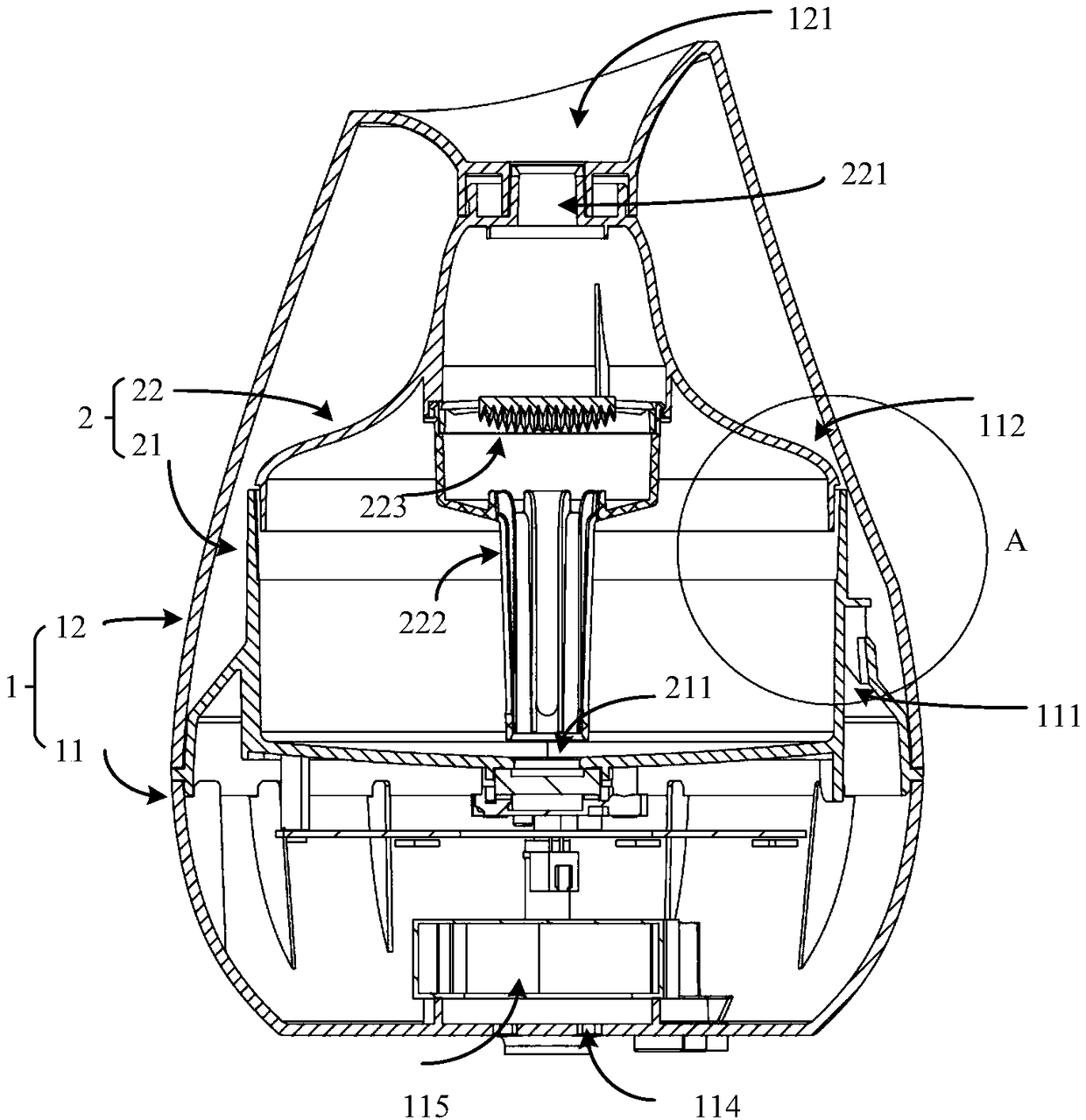
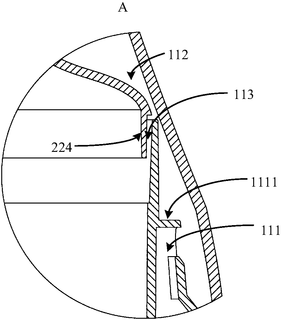
[0031] see figure 1 and figure 2 , the present embodiment provides an atomizing humidifier capable of annular air intake, which includes a main body 1 and a water tank 2 disposed in the main body 1, the main body 1 includes a base 11 and a housing 12 disposed on the base 11, the base 11 is provided with The first air inlet 111 forms an annular air duct 112 between the casing 12 and the water tank 2, and the 360-degree circumference of the water tank 2 is provided with an annular air inlet 113. The wind enters the annular air duct 112 from the first air inlet 111, and then passes through the annular air inlet The tuyere 113 enters in the water tank 2 . Specifically, the water tank 2 is arranged on the upper side of the base 11, and the water tank 2 is covered by the shell 12, and the shell 12 can be freely arranged according to the external shape of the humidifier, so that there is a gap between the shell 12 and the water tank 2, and the gap surrounds the In the 360 ​​degree...


PUM


Abstract

The invention relates to the field of humidifiers, in particular to an annular air inlet atomizing humidifier. The humidifier comprises a main body and a water tank which is arranged in the main body,the main body comprises a base and a shell arranged on the base, wherein a first air inlet is formed in the base, and an annular air duct is formed between the shell and the water tank; and an annular air inlet is formed in the 360-degree circumferential direction of the water tank. According to the annular air inlet atomizing humidifier, air is blown into the water tank from 360 degrees throughan annular air inlet mode , so that the wind power is converged to the middle of the water tank, and then the water mist generated by an atomizing generator is vertically brought out; the air flow path is single, the water mist cannot diffuse freely, the utilization rate is high, so that the atomization efficiency is greatly improved; and in addition, the water mist cannot overflow to other positions in the humidifier, water beads cannot be generated at the positions, such as a shell and the like, like a traditional humidifier, so that a lot of inconvenience is caused, and user experience is influenced.

Description

【Technical field】 [0001] The invention relates to the field of humidifiers, in particular to an atomizing humidifier capable of annular air intake. 【Background technique】 [0002] Humidification products currently on the market are limited by the technology and cost of the atomizer itself, and the amount of fog produced cannot meet the user's experience. In order to increase the amount of mist output, designers usually use methods such as increasing the power consumption of the atomizer, increasing the air volume of the fan, etc., but this will greatly increase the production cost and use cost; in terms of structural design, most humidifiers will make The mist diffuses in the water tank, and the mist is brought out by air convection. The traditional humidifier water tank enters the air through an air inlet, and the air intake direction is single. Due to the large space in the water tank, the fog outlet of the humidifier is small. There are many circulation paths in the wate...

Claims


Application Information

Patent Timeline
Patent Type & Authority Applications(China)
IPC IPC(8): F24F6/14F24F13/00
CPCF24F6/14F24F13/00
Inventor 占旺发
Owner SHENZHEN QIANHAI PATUOXUN NETWORK & TECH CO LTD
Learn More