
Locating device for annular workpiece

A technology for positioning devices and workpieces, applied in positioning devices, metal processing machinery parts, manufacturing tools, etc., can solve the problems of affecting the processing accuracy, the inability to process the side of the workpiece, and the skewing of the workpiece clamping, etc., to achieve firm clamping and contact The effect of many faces

Inactive Publication Date: 2018-08-14
WUHU TIANMENG INFORMATION TECH CO LTD
View PDF0 Cites 13 Cited by
  • Summary
  • Abstract
  • Description
  • Claims
  • Application Information

AI Technical Summary

Problems solved by technology

[0002] For circular workpieces such as flanges, three-jaw chucks are generally used for clamping and fixing, but the clamping of circular workpieces by three-jaw chucks has certain limitations. The three-jaw chuck completes the clamping by clamping the side wall of the workpiece. fixed, but at the same time it is impossible to process the side of the workpiece, and the three-jaw chuck is only suitable for some workpieces with small diameters. For workpieces with large diameters and small thicknesses, the workpiece is prone to skew when clamping, which affects processing. precision

Method used


Image

  • Locating device for annular workpiece
  • Locating device for annular workpiece
  • Locating device for annular workpiece

Examples


specific Embodiment approach

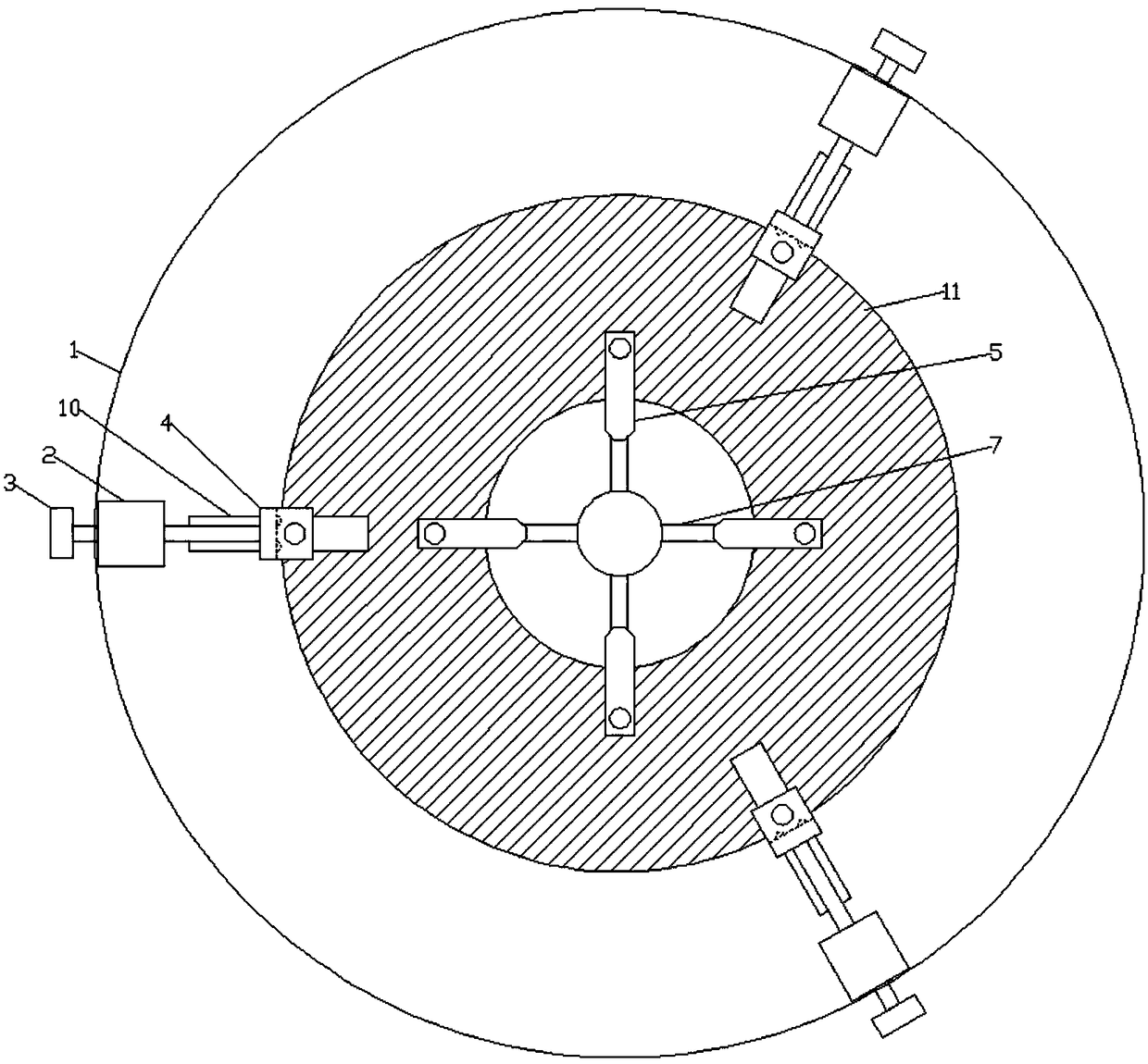
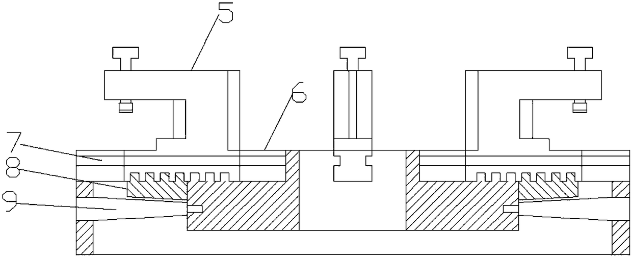
[0018] Figure 1-6 Show the specific embodiment of the present invention: a kind of positioning device of circular ring type workpiece, comprises chassis 1, and described chassis 1 is provided with three chute-10s that are evenly distributed about the center of chassis 1 circle, and described chute-10 is provided with There is a clamp block one 4 that is slidingly connected, and the chassis 1 is also provided with three fixed seats 2 and are all located on one side of the chute one 10, and the fixed seat 2 is provided with a threaded rotating rod 3, and the rotating rod 3 is arranged on the fixed seat 2. The front end of the rod 3 is connected with the clamping block one 4, the clamping block one 4 is a concave structure, the upper end is provided with a threaded pressure rod one 41, the lower end of the pressure rod one 41 is provided with a pressure head one 42, and the pressure rod one 41 lower end is provided with a pressure head one 42. The bottom of the head one 42 is pr...


PUM


Abstract

The invention discloses a locating device for an annular workpiece. The locating device comprises a bottom disk; three sliding grooves I uniformly distributed with respect to a circle center of the bottom disk are formed in the bottom disk; clamping blocks I connected in a sliding manner are arranged in the sliding grooves I; three fixing seats are further arranged on the bottom disk; rotating rods are arranged on the fixing seats; pressure rods I are arranged at the upper ends of the clamping blocks I; pressure heads I are arranged at the lower ends of the pressure rods I; supporting faces Iare arranged below the pressure heads I; a disk body is arranged in the center of the bottom disk; sliding grooves II are formed in the upper end of the disk body; clamping blocks II are arranged in the sliding grooves II; pressure rods II are arranged at the upper ends of the clamping blocks II; pressure heads II are arranged at the bottoms of the pressure rods II; outer tapered bulges are arranged on the outer sides of the clamping blocks II; inner tapered bulges are arranged on the inner sides of the clamping blocks II; supporting faces II are arranged on the bottom faces of the inner sidesof the clamping blocks II; plane thread teeth are formed at the bottoms of the clamping blocks II; the interior of the disk body is connected with a disk wire in a sleeved manner; and four bevel gears are arranged in the disk body. The locating device is wide in part clamping scope, errors due to edge deflection of a part with the relatively large diameter can be eliminated effectively, the machining on all the positions of the part can be achieved, and the locating device has the very good generalization property.

Description

technical field [0001] The invention relates to the field of fixtures, in particular to a positioning device for circular ring workpieces. Background technique [0002] For circular workpieces such as flanges, three-jaw chucks are generally used for clamping and fixing, but the clamping of circular workpieces by three-jaw chucks has certain limitations. The three-jaw chuck completes the clamping by clamping the side wall of the workpiece. fixed, but at the same time it is impossible to process the side of the workpiece, and the three-jaw chuck is only suitable for some workpieces with small diameters. For workpieces with large diameters and small thicknesses, the workpiece is prone to skew when clamping, which affects processing. precision. Contents of the invention [0003] The technical problem to be solved by the present invention is to provide a positioning device for circular ring workpieces, so as to solve the above-mentioned multiple defects in the prior art. [0...

Claims


Application Information

Patent Timeline
Patent Type & Authority Applications(China)
IPC IPC(8): B23Q3/06
CPCB23Q3/062
Inventor 钟明
Owner WUHU TIANMENG INFORMATION TECH CO LTD
Learn More