
Remote monitoring system of power distribution cabinet

A technology of remote monitoring system and power distribution cabinet, which is applied in the field of remote monitoring system of power distribution cabinet, and can solve problems such as theft of distribution cabinets, large electrical components and lines, and difficulty in further tracking of thieves

Inactive Publication Date: 2018-08-10
佛山杰致信息科技有限公司
View PDF4 Cites 14 Cited by
  • Summary
  • Abstract
  • Description
  • Claims
  • Application Information

AI Technical Summary

Problems solved by technology

When the existing power distribution cabinet is in use, due to the high value of the electrical components and lines inside the power distribution cabinet, theft of the power distribution cabinet often occurs, because the existing power distribution cabinet is not equipped with security monitoring during installation The system makes the frequent occurrence of stolen distribution cabinets, and it is difficult to further track the thieves after the power distribution cabinet is stolen, which brings certain troubles to people. For this reason, we propose a remote monitoring system for power distribution cabinets

Method used


Image

  • Remote monitoring system of power distribution cabinet
  • Remote monitoring system of power distribution cabinet

Examples


Embodiment Construction

[0018] The following will clearly and completely describe the technical solutions in the embodiments of the present invention with reference to the accompanying drawings in the embodiments of the present invention. Obviously, the described embodiments are only some, not all, embodiments of the present invention.

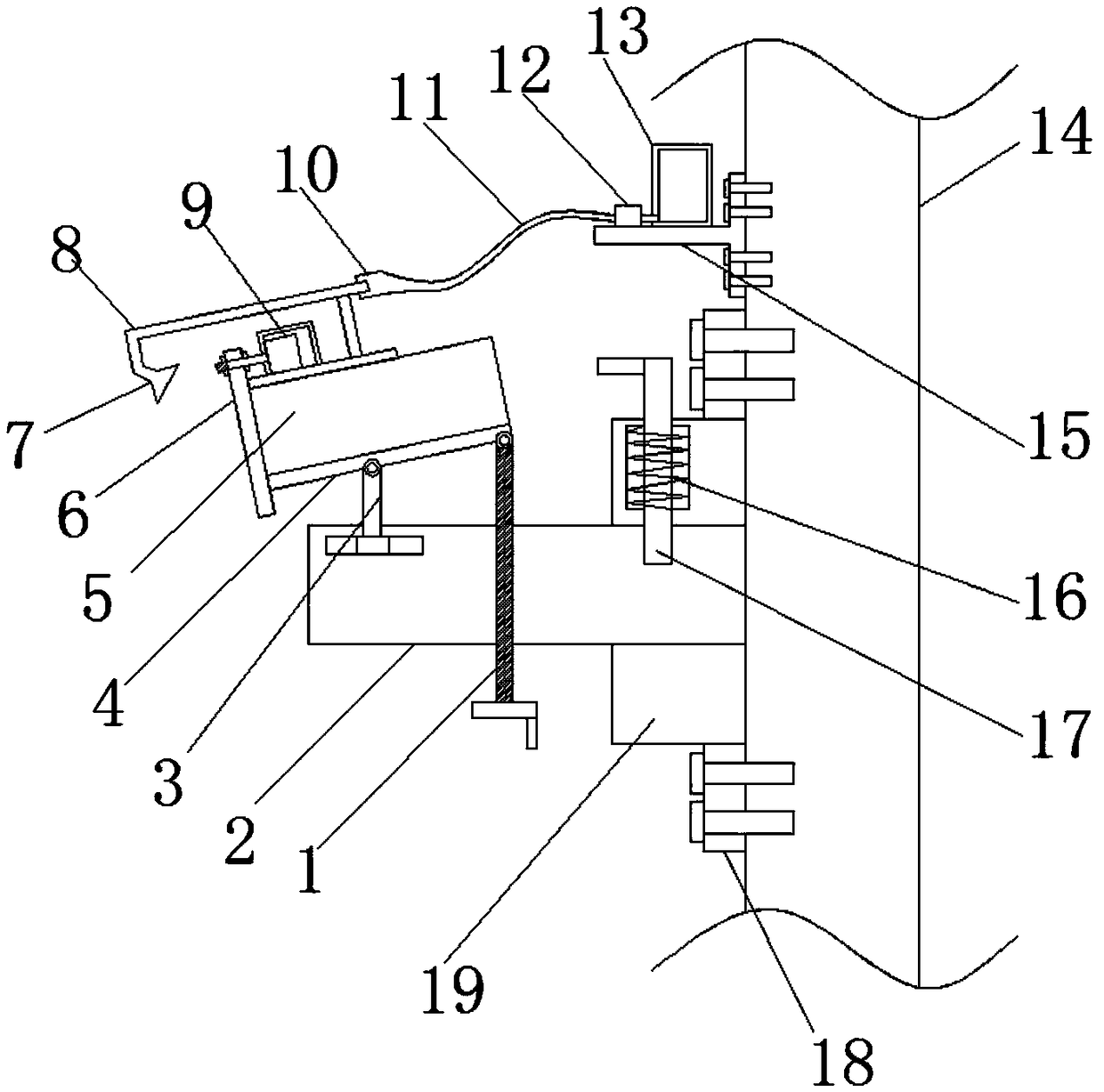
[0019] refer to Figure 1-2 , a remote monitoring system for a power distribution cabinet, comprising a wall 14, the side wall of the wall 14 is fixed with a mounting block 19 by bolts, and the vertical section of the mounting block 19 is circular, and the side wall of the mounting block 19 is welded There are a plurality of evenly distributed protrusions 18, and the mounting block 19 is fixed on the wall 14 by bolts of the protrusions 18, and the center position of the side wall of the mounting block 19 away from the wall 14 is clamped with a horizontally arranged mounting column 2. The top side of the column 2 away from the mounting block 19 is slidably connected w...


PUM


Abstract

The invention discloses a remote monitoring system of a power distribution cabinet. The remote monitoring system comprises a wall body, an installing block is fixed on the side wall of the wall body through a bolt, and a vertical section of the installing block is circular; multiple uniformly distributed bumps are welded on the side wall of the installing block, and the installing block is fixed on the wall body through a bump bolt; a horizontally arranged installing column is clamped at the center location of the side wall of one side of the installing block far away from the wall body, andone side of the top end of the installing column far away from the installing block is in sliding connection with a vertically arranged strut; a vertically arranged threaded rod is in threaded connection with the installing column, and the thread rod penetrates the installing block and is located between the strut and the installing block; the top ends of the thread rod and the strut are hinged with a first installing plate, and the thread rod is in rotatable connection with the first installing plate. The device disclosed by the inventio is simple in structure, novel in design, capable of monitoring the power distribution cabinet in real time and convenient for installing and dismounting, and capable of automatically cleaning the camera surface at fixed time, strong in practicability andsuitable for popularization.

Description

technical field [0001] The invention relates to the technical field of remote monitoring, in particular to a remote monitoring system of a power distribution cabinet. Background technique [0002] Surveillance cameras are generally camera devices used to monitor specific areas in real time. Surveillance cameras have been widely used in various security protection fields. When the existing power distribution cabinet is in use, due to the high value of the electrical components and lines inside the power distribution cabinet, theft of the power distribution cabinet often occurs, because the existing power distribution cabinet is not equipped with security monitoring during installation The system makes the frequent occurrence of stolen distribution cabinets, and it is difficult to further track the thieves after the power distribution cabinet is stolen, which brings certain troubles to people. For this reason, we propose a remote monitoring system for power distribution cabine...

Claims


Application Information

Patent Timeline
Patent Type & Authority Applications(China)
IPC IPC(8): H04N7/18F16M13/02F16M11/10B08B3/02B08B1/04
CPCH04N7/18F16M11/10F16M13/02B08B3/02B08B1/32B08B1/12
Inventor 王玉环
Owner 佛山杰致信息科技有限公司
Learn More