
Piezoelectric energy collection apparatus

A piezoelectric and energy-collecting technology, applied in circuit devices, battery circuit devices, current collectors, etc., can solve problems such as lack of conversion rate, low conversion rate of mechanical energy, and energy waste

Inactive Publication Date: 2018-08-10
NINGBO INST OF TECH ZHEJIANG UNIV ZHEJIANG
View PDF5 Cites 0 Cited by
  • Summary
  • Abstract
  • Description
  • Claims
  • Application Information

AI Technical Summary

Problems solved by technology

[0003] However, there are some defects in the utilization method of the piezoelectric sheet in the prior art. In actual operation, the piezoelectric sheet is placed on a certain support, and pressure is applied to the piezoelectric sheet. When the piezoelectric sheet is pressed down, the piezoelectric sheet shrinks and deforms. The piezoelectric sheet rebounds and resets, and uses contraction to reset to convert mechanical energy into electrical energy. However, most of the energy of the piezoelectric sheet will be dissipated from the support during the contraction and rebound process, resulting in a low conversion rate of mechanical energy into electrical energy, resulting in energy loss. waste of
Therefore, there is currently a lack of piezoelectric energy collectors with high conversion rates and avoiding energy waste.

Method used


Image

  • Piezoelectric energy collection apparatus
  • Piezoelectric energy collection apparatus
  • Piezoelectric energy collection apparatus

Examples


Embodiment Construction

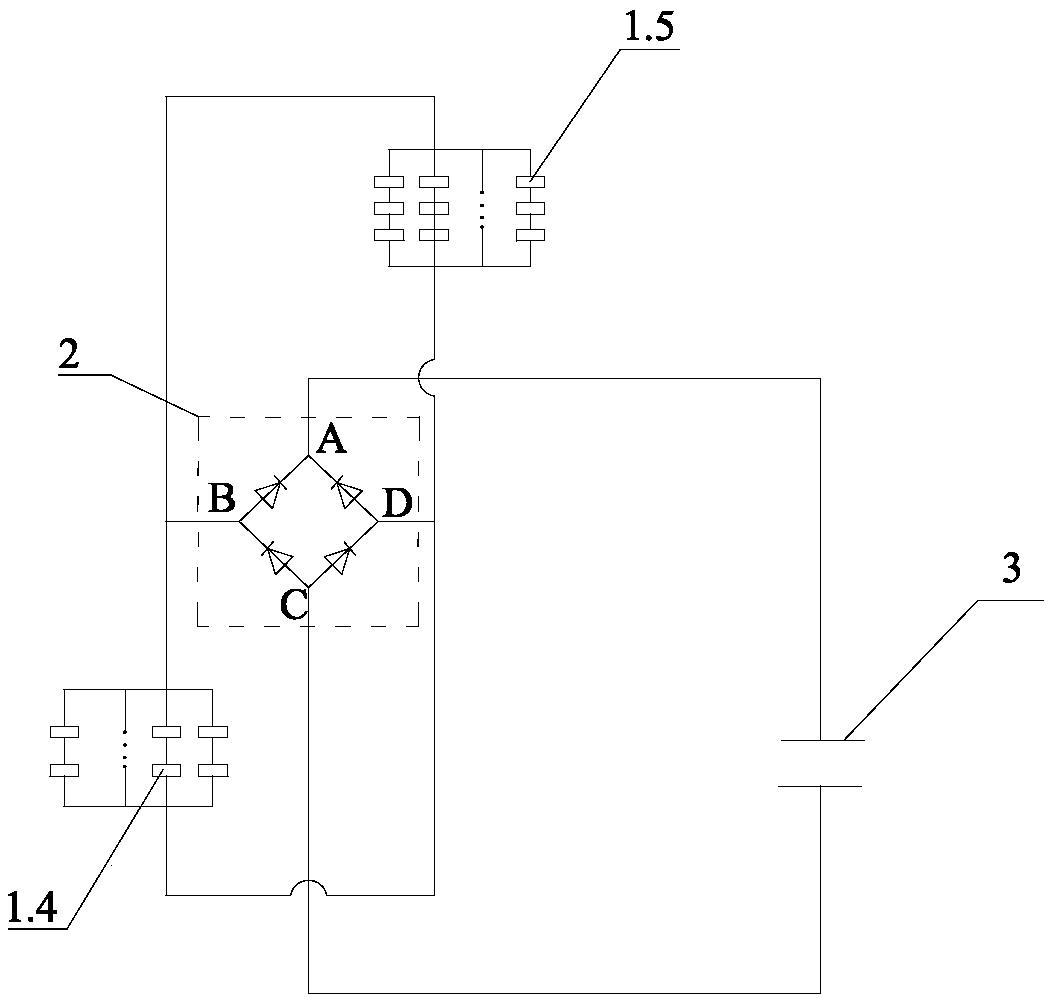
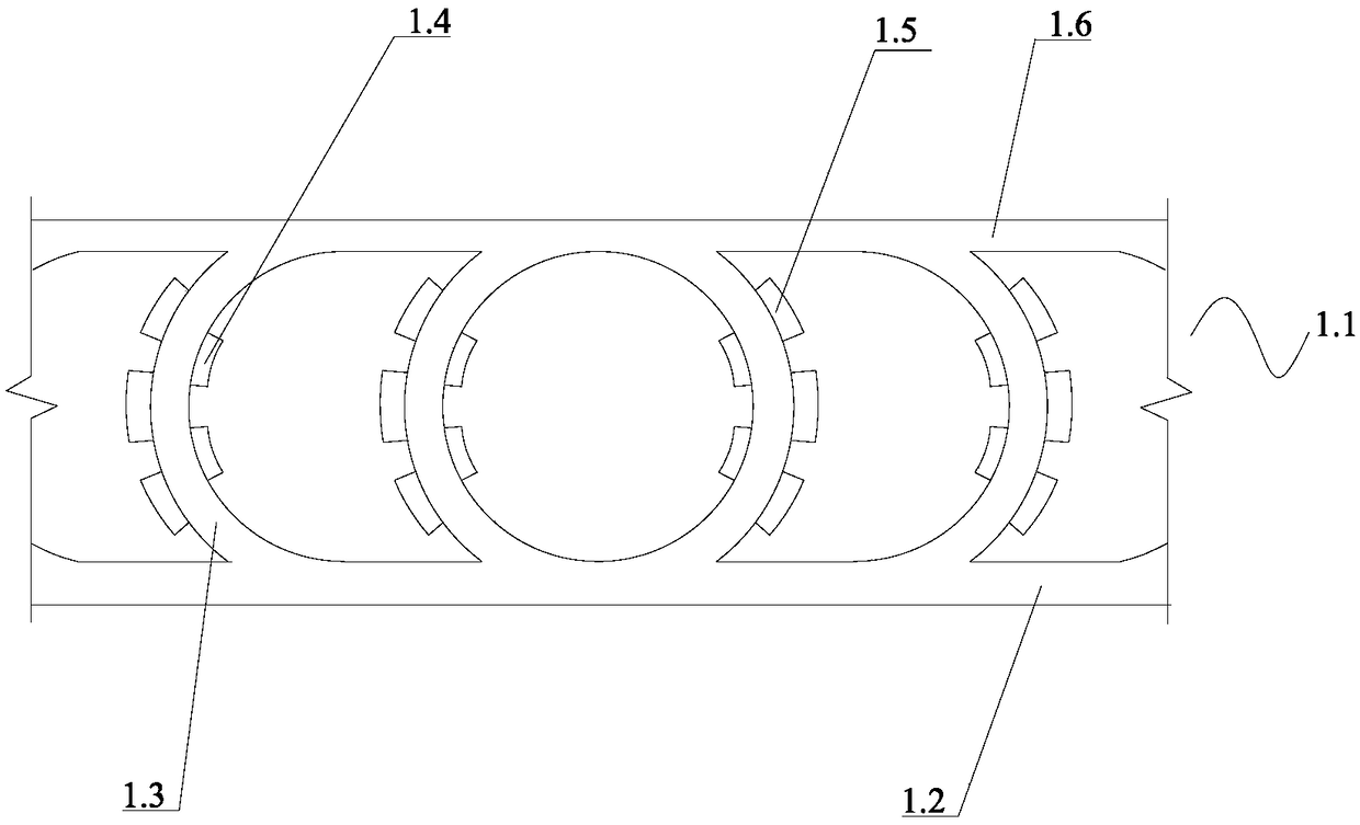
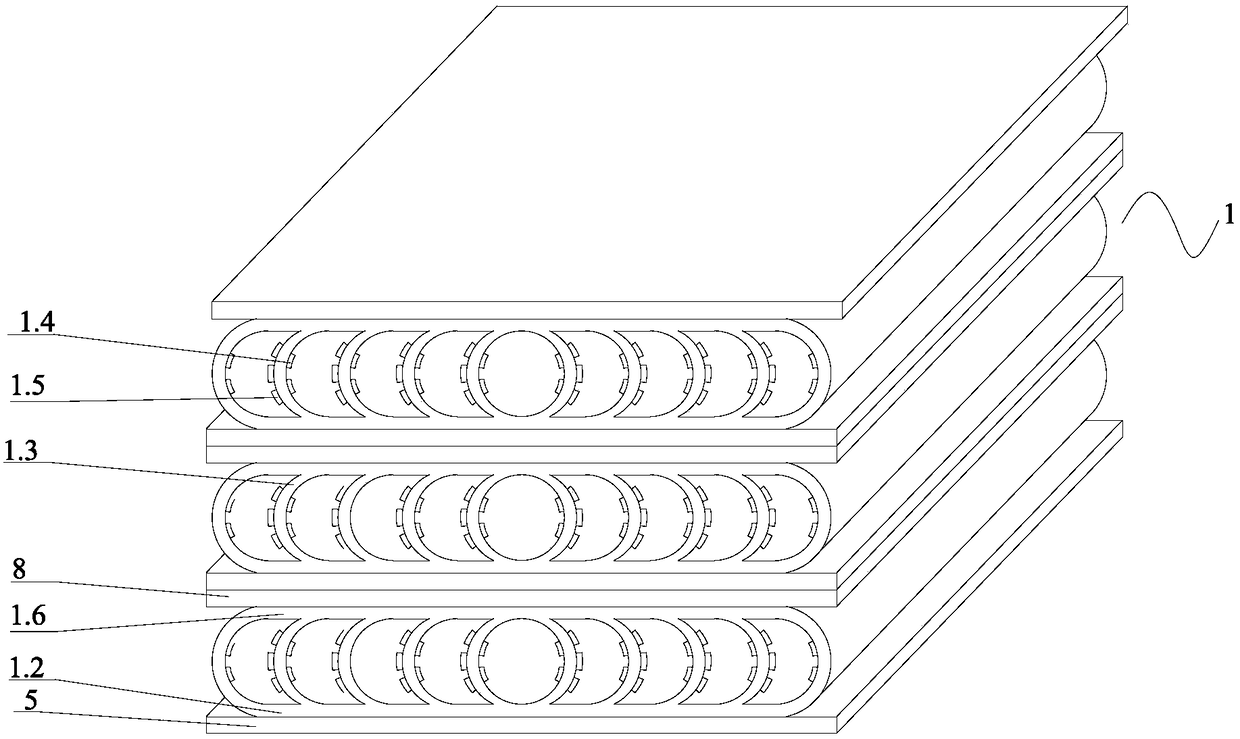
[0024] Such as figure 1 , figure 2 , image 3 As shown, an embodiment of the piezoelectric energy collecting device of the present invention includes a piezoelectric support 1, a bridge rectifier 2 and a capacitor 3, and the bridge rectifier 2 and the capacitor 3 are connected in series.

[0025] The piezoelectric support 1 includes a multilayer piezoelectric energy collection unit 1.1, each piezoelectric energy collection unit 1.1 includes an upper plate 1.6, a lower plate 1.2, and a plurality of elastic materials are fixed between the upper plate 1.6 and the lower plate 1.2. The curved sheet 1.3. The curved sheets 1.3 are divided into two groups with left and right symmetry, and all the curved sheets 1.3 are curved outward. The curved sheet 1.3 is made of memory metal, rubber or thermoplastic elastomer.

[0026] The adjacent upper and lower piezoelectric energy collection units 1.1 are connected. First, the bottom surface of the lower plate 1.2 of the upper piezoelectri...


PUM


Abstract

The invention discloses a piezoelectric energy collection apparatus. The piezoelectric energy collection apparatus comprises a piezoelectric bracket, a bridge rectifier and a capacitor; the bridge rectifier and the capacitor are electrically connected; the piezoelectric bracket comprises at least one layer of piezoelectric energy collection unit; each piezoelectric energy collection unit comprisesan upper plate and a lower plate; multiple arc-shaped sheets prepared from an elastic material are fixed between the upper plate and the lower plate; multiple inner wall piezoelectric sheets are fixed on the inner walls of the arc-shaped sheets in an insulating manner; multiple outer wall piezoelectric sheets are fixed on the outer walls of the arc-shaped sheets in an insulating manner; the multiple inner wall piezoelectric sheets on the inner wall of each arc-shaped sheet are connected in series to form an inner wall piezoelectric sheet branch to be electrically connected with the bridge rectifier; and the multiple outer wall piezoelectric sheets on the outer wall of each arc-shaped sheet are connected in series to form an outer wall piezoelectric sheet branch to be electrically connected with the bridge rectifier. The piezoelectric energy collection apparatus is high in conversion rate of mechanical energy and electric energy, and low in waste of energy.

Description

technical field [0001] The invention relates to the technical field of energy conversion equipment, in particular to a piezoelectric energy collection device. Background technique [0002] Piezoelectric sheets can use the unique properties of piezoelectric materials to convert mechanical energy into electrical energy by collecting mechanical energy in the environment, and finally generate piezoelectric micro-energy. Piezoelectric micro-energy has many advantages such as long service life, no pollution, compatibility with MEMS (micro-electromechanical systems) technology, and high energy density, so it has a wide range of application prospects. With the increasing awareness of environmental protection, the demand for green and environmentally friendly energy is increasing, and the application of piezoelectric sheets to achieve energy conversion is becoming more and more common. [0003] However, there are some defects in the utilization method of the piezoelectric sheet in t...

Claims


Application Information

Patent Timeline
Patent Type & Authority Applications(China)
IPC IPC(8): H02J7/32H02N2/18
CPCH02J7/32H02N2/186
Inventor 樊玮洁樊扬祖张军毛江鸿金伟良
Owner NINGBO INST OF TECH ZHEJIANG UNIV ZHEJIANG
Learn More