Double beam magnetic spectrograph

A dual-beam, spectrometer technology, applied in the field of physical measurement, can solve the problems of complex steps, inability to obtain nano-scale magnetization dynamic characteristics, and the effect is easily limited by optical components.

Inactive Publication Date: 2018-08-10
JINHUA VOCATIONAL TECH COLLEGE
View PDF3 Cites 1 Cited by
  • Summary
  • Abstract
  • Description
  • Claims
  • Application Information

AI Technical Summary

Problems solved by technology

The magneto-optical Kerr effect measurement device mainly detects the magnetization observation of the sample surface by detecting the change of the polarization state of a beam of linearly polarized light after it is reflected on the surface of the material. Therefore, the imaging effect is easily limited by the optical elements. Technical defect 1: The spatial resolution of the traditional focusing Kerr microscope using the microscope objective lens is determined by the optical diffraction limit, so it is impossible to obtain the dynamic characteristics of magnetization at the nanometer scale
In recent years, the secondary magneto-optical Kerr effect has been observed in some magnetic samples. The detection of the secondary magneto-optical Kerr effect is different from the traditional magneto-optical Kerr effect measurement. The second defect of the existing technology: the The secondary magneto-optical Kerr effect data needs to be compared with the traditional magneto-optic Kerr effect data for calibration. Therefore, in the prior art, it is necessary to change the structure of the test device in the same experimental process to complete the experiment. The steps are relatively complicated, so A kind of dual-beam magnetic spectrometer can solve the problem

Method used


Image

  • Double beam magnetic spectrograph

Examples


Embodiment Construction

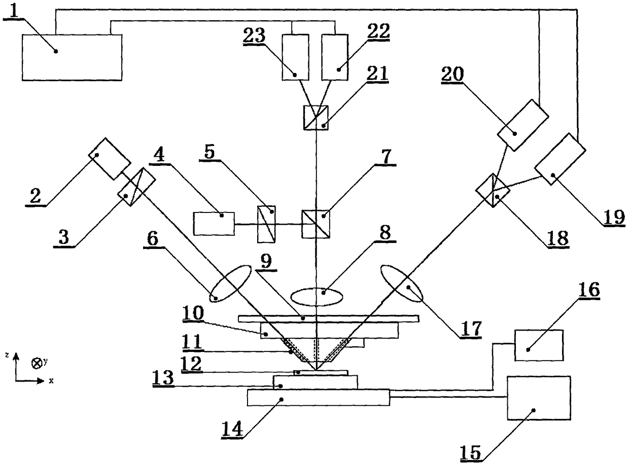
[0024] like figure 1It is a schematic diagram of the present invention, the lower left corner has an xyz three-dimensional direction mark, xyz is a spatial rectangular coordinate system, the xy plane is a horizontal plane, and the zx plane is perpendicular to the horizontal plane. The two-beam magnetic spectrometer mainly includes a computer 1, a laser I2, and a polarizer I3 , laser II4, polarizer II5, convex lens I6, beam splitter 7, convex lens II8, lens stand 9, atomic force microscope 10, probe 11, sample 12, sample stage 13, magnet 14, signal generator 15, oscilloscope 16, convex lens III17, Wollaston prism I18, detector I19, detector II20, Wollaston prism II21, detector III22, detector IV23, the probe 11 is located at the lower end of the atomic force microscope 10, and the sample 12 is located on the sample stage 13. The sample 12, the sample stage 13, and the magnet 14 are located below the probe 11 in sequence. The probe 11 is an atomic force microscope probe and is i...


PUM


Abstract

The invention relates to the technical field of physical measurement and discloses a double beam magnetic spectrograph. The double beam magnetic spectrograph comprises a computer, a laser device I, apolaroid I, a laser device II, a polaroid II, a convex lens I, a beam splitter, a convex lens II, a lens platform, an atomic force microscope, a probe, a sample, a sample platform, a magnet, a signalgenerator, an oscilloscope, a convex lens III, a Wollaston prism I, a detector I, a detector II, a Wollaston prism II, a detector III and a detector IV. A through hole I, a through hole II and a through hole III are formed in the probe in an axial direction of a circular truncated cone, the through hole II is distributed in the axial direction of the circular truncated cone of the probe, the included angle between the axis of the through hole I and the axis of the through hole II is positive 45 degrees, and the included angle between the axis of the through hole III and the through hole II isnegative 45 degrees. The incidence angle of a laser beam I is 45 degrees, the incidence angle of a laser beam II is 90 degrees, the intensity of reflected light is recorded by two detectors separately, and the difference value of the intensity of the reflected light is analyzed; a secondary magnetooptic Kerr effect signal and a longitudinal magnetooptic Kerr effect signal of the sample can be measured at the same time without changing the structure of the spectrograph.

Description

technical field [0001] The invention relates to the technical field of physical measurement, in particular to a double-beam magnetic spectrometer for studying the secondary magneto-optical Kerr effect of a single nanostructure on the surface of a material. Background technique [0002] The magneto-optical Kerr effect measurement device is an important means in the study of material surface magnetism. Its working principle is based on the magneto-optic Kerr effect caused by the interaction between light and magnetized media. Magnetic detection, and non-contact measurement can be realized, and it has important applications in the research of magnetic order, magnetic anisotropy, interlayer coupling and phase transition behavior of magnetic ultrathin films. The magneto-optical Kerr effect measurement device mainly detects the magnetization observation of the sample surface by detecting the change of the polarization state of a beam of linearly polarized light after it is reflect...

Claims


Application Information

Patent Timeline
Patent Type & Authority Applications(China)
IPC IPC(8): G01R33/12G01Q60/24
CPCG01Q60/24G01R33/12
Inventor 张向平方晓华陈兴威
Owner JINHUA VOCATIONAL TECH COLLEGE
Why Eureka
Try Eureka