
Optical fiber sensor with air membrane cooling function

An optical fiber sensor and air film cooling technology, which is applied to instruments, optical devices, measuring devices, etc., can solve the problems of manual operation, cleaning products cannot be reused, and fiber probe cleaning, etc., and achieves reasonable and novel design. Simple structure and convenient operation

Pending Publication Date: 2018-08-10
NANJING INST OF TECH
View PDF0 Cites 0 Cited by
  • Summary
  • Abstract
  • Description
  • Claims
  • Application Information

AI Technical Summary

Problems solved by technology

Although these products have a good effect on cleaning optical fiber pollution, they still have certain limitations, such as the fiber optic probe cannot be cleaned during the measurement process, the cleaning work needs to be completed manually, and cleaning products cannot be reused, etc.

Method used


Image

  • Optical fiber sensor with air membrane cooling function
  • Optical fiber sensor with air membrane cooling function

Examples


Embodiment Construction

[0013] In order to deepen the understanding of the present invention, the present invention will be described in further detail below in conjunction with the accompanying drawings and embodiments, which are only used to explain the present invention and do not limit the protection scope of the present invention.

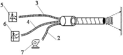
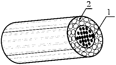
[0014] like Figure 1-2 As shown, the present invention is a fiber optic sensor with film cooling. Taking a reflective optical fiber displacement sensor as an example, the sensor includes a reflective optical fiber displacement sensor probe 1, a capillary catheter 2, a light source 5, a photoelectric converter 6 and a Adjust the gas pump 7, the capillary conduit 2 is tightly fixed on the periphery of the reflective optical fiber displacement sensor probe 1 in a symmetrical distribution form, and the capillary conduit 2 is tightly fixed on the reflective optical fiber displacement sensor probe in the form of bonding, single-turn or multi-turn 1 periphery, the end face...


PUM


Abstract

The invention relates to an optical fiber sensor with an air membrane cooling function. The optical fiber sensor comprises a probe, capillary guide tubes, a light source, a photoelectric converter andan adjustable air pump. The capillary guide tubes are tightly fixed to the periphery of the probe in a symmetric distribution mode, the other ends of the capillary guide tubes are connected to the adjustable air pump, the adjustable air pump sends low temperature gas into the capillary guide tubes to form a low temperature air membrane on the surface of the probe, the probe is composed of one endof a transmitting optical fiber bundle and one end of a receiving optical fiber bundle, the other end of the transmitting optical fiber bundle is connected to the light source, and the other end of the receiving optical fiber bundle is connected to a photoelectric converter. The optical fiber sensor is simple in structure, reasonable and novel in design and convenient to operate, pollutants of the sensor probe caused by oil stains, dust and the like in an environment where the measurement sensor probe is located can be prevented and cleaned out actively in real time in the process of detecting the displacement of the sensor, and a certain cooling effect on the sensor is achieved.

Description

technical field [0001] The invention belongs to the field of test and measurement, and in particular relates to an optical fiber sensor with air film cooling. Background technique [0002] Optical fiber sensors have a series of unique advantages due to the characteristics of good light transmission characteristics of optical fibers, wide transmission frequency bandwidth, low loss, high temperature resistance, corrosion resistance, and electromagnetic interference resistance, such as no electromagnetic interference, corrosion resistance; Source real-time monitoring, electrical insulation, good explosion-proof; small size, light weight, can be bent; high sensitivity, long service life, etc. [0003] However, during the use of the optical fiber displacement sensor, the surface of the probe is easily polluted, and there are many sources of pollution, including: oil stains, dust, condensed vapor (air) film residue, evaporation of other solvents, etc., which directly affect the re...

Claims


Application Information

Patent Timeline
Patent Type & Authority Applications(China)
IPC IPC(8): G01D3/036G01B11/02
CPCG01B11/02G01D3/036
Inventor 贾丙辉何磊
Owner NANJING INST OF TECH
Learn More