
Drilling liner hanger controlled by surface bit weight and control method of drilling liner hanger

A technology of a liner hanger and a control method, which is applied in the field of oil and gas field drilling, can solve the problems that the pressure of the liquid column in the pipe cannot pass through the pressure transmission hole, and the liner hanger cannot be seated, so as to achieve reliable seating, avoid interference, and operate simple effect

Inactive Publication Date: 2018-08-10
JIANGSU AERO SPACE HONGPENG NUMERICAL CONTROL MACHINERY
View PDF6 Cites 1 Cited by
  • Summary
  • Abstract
  • Description
  • Claims
  • Application Information

AI Technical Summary

Problems solved by technology

The biggest problem with this method of sitting and hanging is that the inner wall of the liner hanger needs to be provided with pressure transmission holes, which are connected to the liquid in the pipe, and the pressure of the liquid column in the pipe acts on the slips through the pressure transmission holes. Due to the blockage due to the many impurities in the downhole, the pressure of the liquid column in the pipe cannot be applied to the slips through the pressure transmission hole, resulting in the problem that the liner hanger cannot be mounted; on the other hand, if the liner hanger is in the process of going into the well When the pressure in the pipe increases abnormally, the liner hanger will be suspended in advance, which will bring unnecessary downhole complications

Method used


Image

  • Drilling liner hanger controlled by surface bit weight and control method of drilling liner hanger
  • Drilling liner hanger controlled by surface bit weight and control method of drilling liner hanger
  • Drilling liner hanger controlled by surface bit weight and control method of drilling liner hanger

Examples


Embodiment Construction

[0024] The present invention will be further explained below in conjunction with the accompanying drawings and specific embodiments. It should be understood that the following specific embodiments are only used to illustrate the present invention and are not intended to limit the scope of the present invention. It should be noted that the words "front", "rear", "left", "right", "upper" and "lower" used in the following description refer to the directions in the drawings, and the words "inner" and "outer ” refer to directions towards or away from the geometric center of a particular part, respectively.

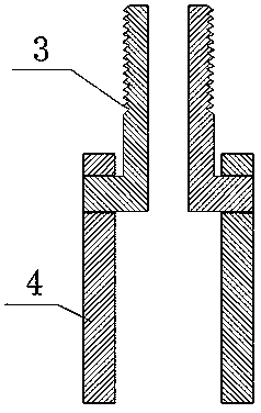
[0025] Such as figure 1 Shown is a liner 16 hanger controlled by the rotation of the drill pipe 15 on the ground, including a lifting short joint 1, a sealing joint 2, slips 3, a motor outer shell 4, a strain gauge 5, a downhole circuit board 6, and a motor rotor 7. Motor inner housing 9, downhole battery 10, coupling sleeve 11, lower joint 13 and upper joint 14, motor rotor 7...


PUM


Abstract

The invention discloses a drilling liner hanger controlled by surface bit weight and a control method of the drilling liner hanger. The control method of the drilling liner hanger comprises the stepsof: a, connecting the upper end of the drilling liner hanger with a drilling rod and the upper end of the drilling liner hanger with a drilling liner, b, operating the drilling rod to ascend and descend according to a certain rule when hanging of the drilling liner hanger is performed after the lower end of the drilling liner is contacted with a shaft bottom, setting a pressure threshold in advance, setting as '1' when the pressured borne by the drilling liner hanger is greater than the threshold and as '0' when the pressured borne by the drilling liner hanger is less than the threshold, and c, performing a hanging task after the drilling liner hanger receives a control instruction. The drilling liner hanger is internally provided with a battery, a motor, a strain gauge and an undergroundcircuit board; and when the hanging of the drilling liner hanger is required to be performed, an operator achieves the hanging of the drilling liner hanger by raising and lowering the drilling rod.

Description

technical field [0001] The invention relates to the technical field of drilling in oil and gas fields, in particular to a liner hanger controlled by ground drilling pressure and a control method thereof. Background technique [0002] When drilling in the oil field, during the liner cementing process, the liner hanger needs to be hung on the upper casing through the slip seat to support the liner connected at the lower part. The currently used general liner hanger set-up method is to hold the pressure at the wellhead, use the pressure difference of the liquid column inside and outside the pipe to push the slips to move upwards, and hang the slips on the upper casing. The biggest problem with this method of sitting and hanging is that the inner wall of the liner hanger needs to be provided with pressure transmission holes, which are connected to the liquid in the pipe, and the pressure of the liquid column in the pipe acts on the slips through the pressure transmission holes. ...

Claims


Application Information

Patent Timeline
Patent Type & Authority Applications(China)
IPC IPC(8): E21B33/04
CPCE21B33/0422
Inventor 陈燕杨清海王斌李权姜领
Owner JIANGSU AERO SPACE HONGPENG NUMERICAL CONTROL MACHINERY
Learn More