Rapid locking positioner

A positioner and fast technology, applied in the direction of positioning device, clamping, support, etc., can solve the problems of easy failure, waste, time-consuming and other problems of bolts or nuts, and achieve the effect of shortening the time of clamping

Inactive Publication Date: 2018-08-10
SUZHOU KSC PRECISE MACHINERY
View PDF8 Cites 5 Cited by
  • Summary
  • Abstract
  • Description
  • Claims
  • Application Information

AI Technical Summary

Problems solved by technology

However, this method is time-consuming and inefficient; moreover, over time, bolts or nuts are prone to failure, resulting in unnecessary waste

Method used


Image

  • Rapid locking positioner

Examples


Embodiment Construction

[0012] The specific implementation manners of the present invention will be further described below in conjunction with the drawings and examples. The following examples are only used to illustrate the technical solution of the present invention more clearly, but not to limit the protection scope of the present invention.

[0013] The technical scheme of concrete implementation of the present invention is:

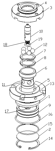
[0014] Such as figure 1 As shown, a quick locking locator includes a base, the base includes a cylinder 1 with two ends open, a cushion plate 2 fixed at the opening of one end of the cylinder 1, and a cushion plate 2 fixed at the other end of the cylinder 1. The baffle plate 3 at the center; the center of the baffle plate 3 is provided with a baffle plate through hole, and the end face of the baffle plate 3 facing away from the cylinder body 1 is provided with a protruding ring 4 located at the periphery of the baffle plate through hole, and the cylinder body 1 There is ...


PUM


Abstract

The invention discloses a rapid locking positioner. The rapid locking positioned comprises a base, the base comprises a cylinder body, a buffer base plate and a baffle, wherein the buffer base plate and the baffle are arranged on the two ends of the cylinder body; a baffle through hole is formed in the center of the baffle, a convex ring is arranged on the end face, back on to the cylinder body, of the baffle, a positioning sleeve with one end penetrating the convex ring is arranged in the cylinder body, a locking head is arranged at the end, located on the outer side of the convex ring, of the positioning sleeve, the outer wall of the end of the positioning sleeve is in threaded connection with a locking nut and an anti-loosening nut, a check ring is arranged on the outer wall of the end,located in the cylinder body, of the positioning sleeve, a piston is arranged between the check ring and the buffer base plate, a spring is connected between the piston and the check ring, a conicallifting pin facing the baffle is arranged on the center of the piston, multiple through holes corresponding to the position of the conical lifting pin are formed in the positioning sleeve, and are evenly distributed in the circumferential direction of the positioning sleeve, and steel balls are arranged in the through holes. The rapid locking positioner is reasonable in structure, precise positioning is achieved while rapid locking is achieved, and the clamping time is shortened.

Description

technical field [0001] The invention relates to a fast locking positioner. Background technique [0002] In the process of workpiece processing, it is generally necessary to clamp and position the workpiece. At present, the locking of the workpiece is usually directly or indirectly locked by bolts, nuts, etc. However, this method takes a long time and has low efficiency; moreover, as time goes by, bolts or nuts are prone to failure, resulting in unnecessary waste. Therefore, there is a need for a locking locator capable of fast locking. Contents of the invention [0003] The object of the present invention is to provide a fast locking positioner, which has a reasonable structure, and can also play a role of precise positioning while realizing fast locking, and shortens the time for clamping. [0004] In order to achieve the stated purpose, the technical solution of the present invention is to design a quick locking locator, including a base, which includes a cylinder wit...

Claims


Application Information

Patent Timeline
Patent Type & Authority Applications(China)
IPC IPC(8): B23Q3/18
CPCB23Q3/18
Inventor 宋秋构
Owner SUZHOU KSC PRECISE MACHINERY
Why Eureka
Try Eureka