
Equipment capable of separating waste liquor generated in industrial production

A kind of equipment and waste liquid technology, which is applied in the field of waste liquid separation equipment, can solve the problems of slow sedimentation rate, material loss, small particles, etc., and achieve the effect of improving crushing efficiency, reducing work difficulty, and obvious separation

Inactive Publication Date: 2018-08-10
赵广海
View PDF0 Cites 1 Cited by
  • Summary
  • Abstract
  • Description
  • Claims
  • Application Information

AI Technical Summary

Problems solved by technology

[0002] In the field of industrial production waste liquid treatment, solid-liquid separation and settling devices are widely used as supporting equipment; traditional solid-liquid separation technology is widely used in various sectors of the national economy such as chemical industry, light industry, pharmaceuticals, mining, metallurgy, energy, environmental protection, etc. ; In the process of material wet processing, because the imperfect process will first affect the product quality, cause material loss, and the pollution to the environment will be more serious, especially the particle suspension, because of its small particles, the sedimentation rate is slow, so The separation efficiency of the particle suspension is reduced; the existing solid-liquid separation and sedimentation device has a single function and the separation effect is not obvious, which makes a lot of resources and energy wasted in the separation process

Method used


Image

  • Equipment capable of separating waste liquor generated in industrial production
  • Equipment capable of separating waste liquor generated in industrial production
  • Equipment capable of separating waste liquor generated in industrial production

Examples


Embodiment Construction

[0019] The following will clearly and completely describe the technical solutions in the embodiments of the present invention with reference to the accompanying drawings in the embodiments of the present invention. Obviously, the described embodiments are only some, not all, embodiments of the present invention. Based on the embodiments of the present invention, all other embodiments obtained by persons of ordinary skill in the art without making creative efforts belong to the protection scope of the present invention.

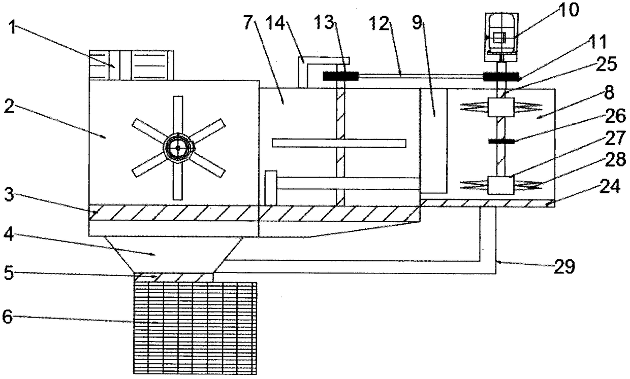
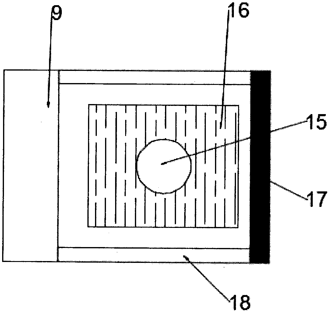
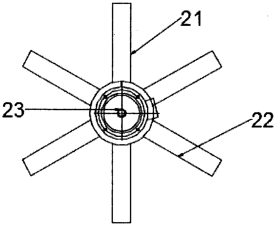
[0020] see Figure 1~4 , in an embodiment of the present invention, a device capable of separating waste liquid generated in industrial production, comprising a feed inlet 1, a first separation chamber 2, a first filter screen 3, a second separation chamber 4, a second filter The net 5 and the waste liquid collection chamber 6, the upper part of the first separation chamber 2 is provided with a feed inlet 1, and a feeding mechanism 21 is installed inside the f...


PUM


Abstract

The invention discloses equipment capable of separating waste liquor generated in industrial production. The equipment comprise a feed opening, a first separation chamber, a first filter screen, a second separation chamber, a second filter screen and a waste liquor collecting chamber, wherein the feed opening is formed in the upper part of the first separation chamber; a feeding mechanism is arranged inside the first separation chamber; the first filter screen is arranged at the bottom of the first separation chamber; the second separation chamber is arranged at the lower part of the first filter screen; the second filter screen is arranged at the lower part of the second separation chamber; the lower part of the second filter screen is connected with the waste liquor collecting chamber; arolling chamber is arranged on the right side of the first separation chamber; a crushing chamber is arranged on the right side of the rolling chamber. The equipment disclosed by the invention has the advantages of energy conservation, environmental protection and reasonable structure; the equipment can sufficiently separate the waste liquor and sufficiently crush residues in the waste liquor andis suitable for popularization.

Description

technical field [0001] The invention relates to the technical field of waste liquid treatment, in particular to a device capable of separating waste liquid produced in industrial production. Background technique [0002] In the field of industrial production waste liquid treatment, solid-liquid separation and settling devices are widely used as supporting equipment; traditional solid-liquid separation technology is widely used in various sectors of the national economy such as chemical industry, light industry, pharmaceuticals, mining, metallurgy, energy, environmental protection, etc. ;In the process of material wet processing, because the imperfect process will first affect the product quality, cause material loss, and the pollution to the environment will be more serious, especially the particle suspension, because of its small particles, the sedimentation rate is slow, so The separation efficiency of the particle suspension is reduced; the existing solid-liquid separatio...

Claims


Application Information

Patent Timeline
IPC IPC(8): B01D29/58B01D29/01B01D29/86B01D29/76B02C18/10B02C1/00
CPCB01D29/58B01D29/01B01D29/76B01D29/86B02C1/00B02C18/10
Inventor 赵广海
Owner 赵广海
Learn More