Anode structure and anode structure manufacturing method

A technology of anode structure and manufacturing method, which is applied in semiconductor/solid-state device manufacturing, electrical components, electric solid-state devices, etc., can solve the problems of easy damage of the anode layer and complicated manufacturing process, and achieve the effect of high reflective performance

Pending Publication Date: 2018-08-07
JITRI INST OF ORGANIC OPTOELECTRONICS CO LTD
View PDF0 Cites 0 Cited by
  • Summary
  • Abstract
  • Description
  • Claims
  • Application Information

AI Technical Summary

Problems solved by technology

[0004] In view of this, the purpose of the present invention is to provide an anode structure and an anode structure manufacturing method to improve the problems in the prior art that the manufacturing process is complicated and the anode layer is easily damaged due to the need to set the anode separation column

Method used


Image

  • Anode structure and anode structure manufacturing method
  • Anode structure and anode structure manufacturing method
  • Anode structure and anode structure manufacturing method

Examples


Embodiment Construction

[0036] In order to make the purpose, technical solutions and advantages of the embodiments of the present invention clearer, the technical solutions in the embodiments of the present invention will be clearly and completely described below in conjunction with the drawings in the embodiments of the present invention. Obviously, the described embodiments It is only a part of embodiments of the present invention, but not all embodiments. The components of the embodiments of the invention generally described and illustrated in the figures herein may be arranged and designed in a variety of different configurations.

[0037] Accordingly, the following detailed description of the embodiments of the invention provided in the accompanying drawings is not intended to limit the scope of the claimed invention, but merely represents selected embodiments of the invention. Based on the embodiments of the present invention, all other embodiments obtained by persons of ordinary skill in the a...


PUM

PropertyMeasurementUnit
thicknessaaaaaaaaaa
thicknessaaaaaaaaaa
thicknessaaaaaaaaaa

Abstract

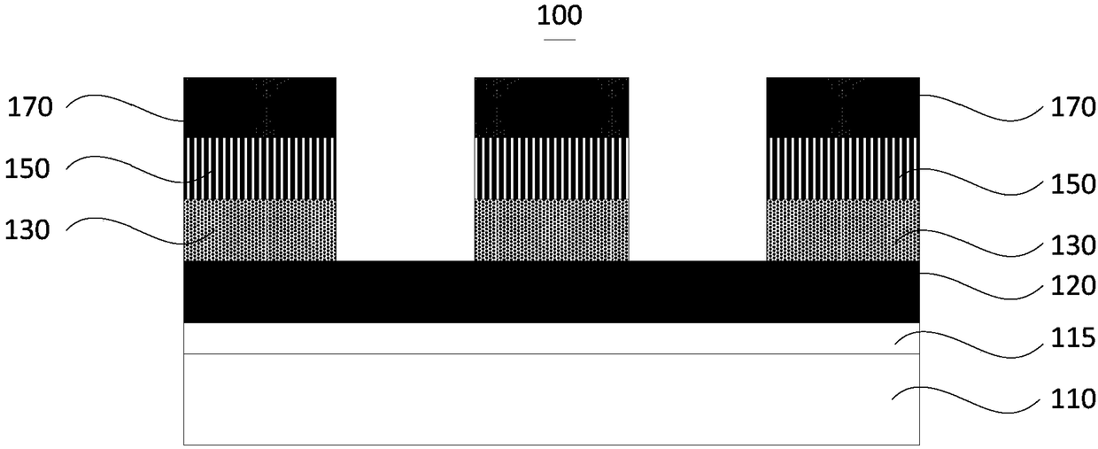
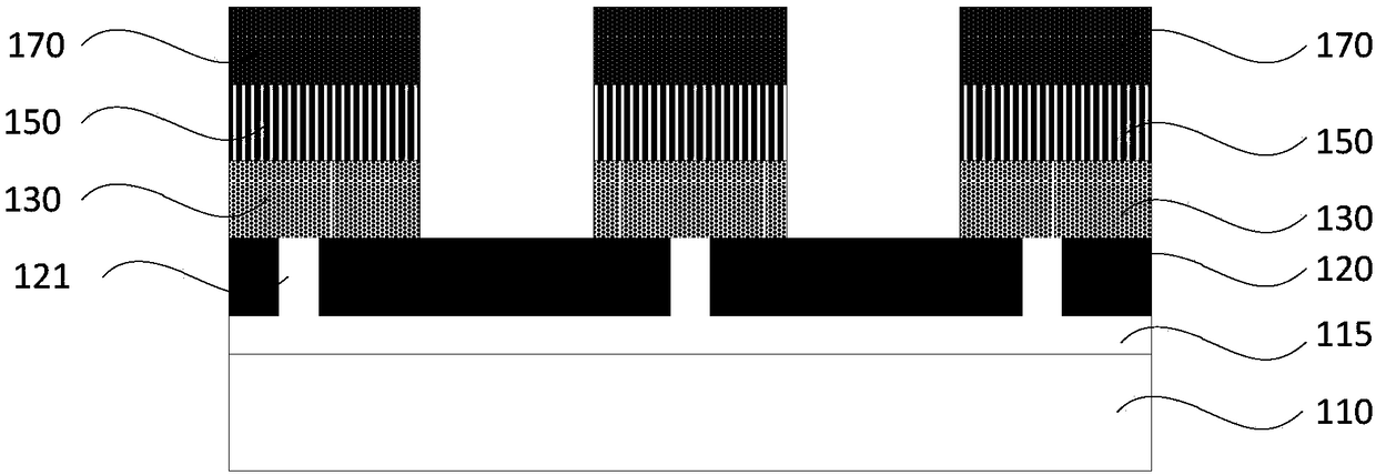
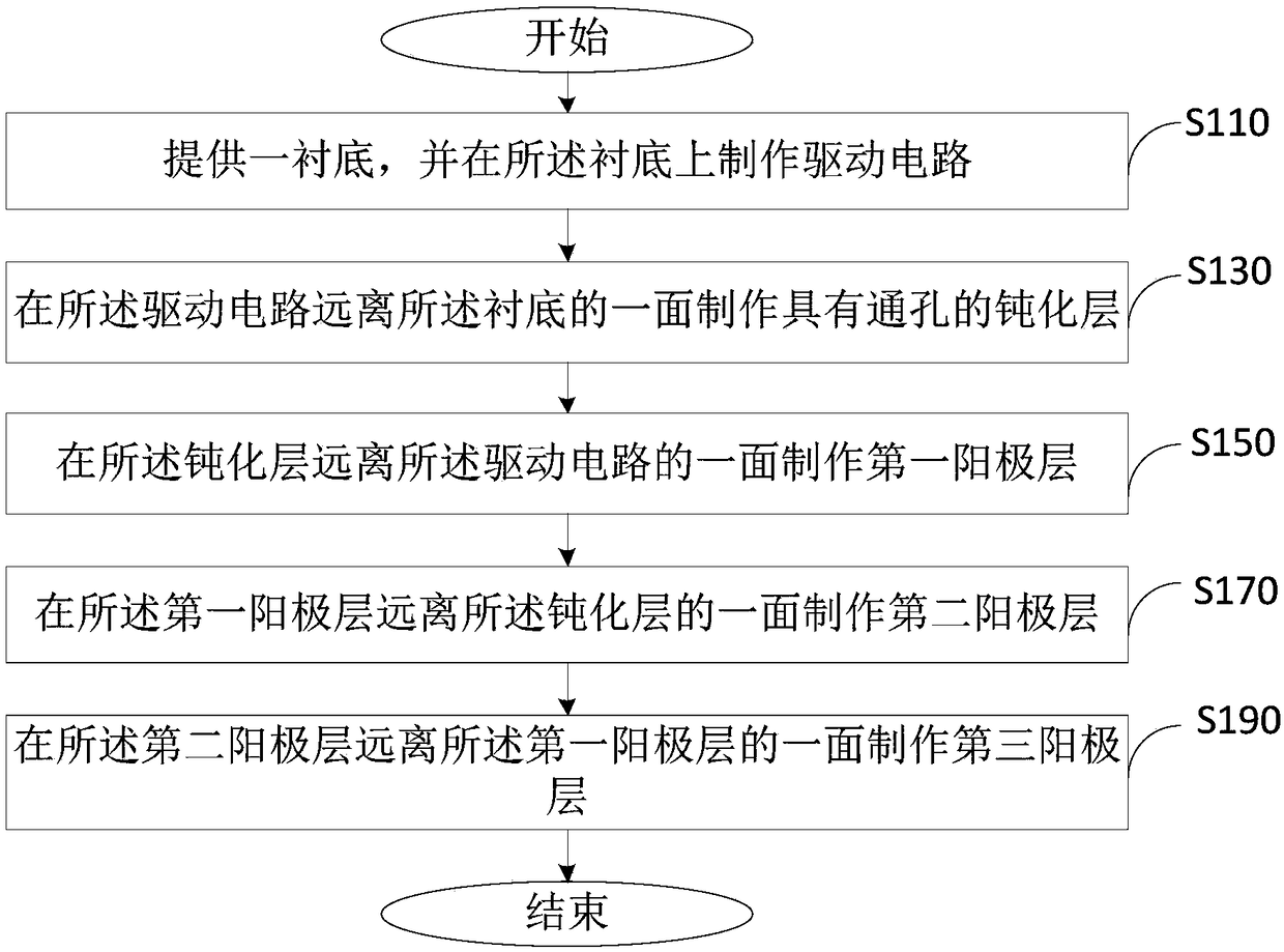
The invention relates to an anode structure and an anode structure manufacturing method and belongs to the semiconductor technological field. The anode structure is composed of a substrate, a drivingcircuit, a passivation layer, first anode layers, second anode layers and third anode layers; the driving circuit is fabricated on the substrate; the passivation layer is fabricated on one side of thedriving circuit, wherein the one side of the driving circuit is far away from the substrate; the first anode layer is fabricated on one side of the passivation layer, wherein the one side of the passivation layer is far away from the driving circuit; the second anode layer is fabricated on one side of the first anode layer, wherein the one side of the first anode layer is far away from the passivation layer; the third anode layer is fabricated on one side of the second anode layer, wherein the one side of the second anode layer is far away from the first anode layer; through holes corresponding to the first anode layers are formed in the passivation layer; the through hole pass through the passivation layer and are filled with a conductive material so as to electrically connect the driving circuit with the first anode layers; and the second anode layer is a Al:Ag structural layer. With the above structure adopted, the problems of complicated manufacturing process and high possibilityof being damaged of anode layers which are caused by the setting of anode spacer columns in the prior art can be solved.

Description

technical field [0001] The invention relates to the technical field of semiconductors, in particular to an anode structure and a method for manufacturing the anode structure. Background technique [0002] With the continuous expansion of the application fields of semiconductor devices, in order to ensure the performance of semiconductor devices, the manufacture of semiconductor devices has received extensive attention. Among them, the reflective performance of the anode structure in the OLED device directly determines the display performance of the OLED device, and aluminum is generally used as the anode material. Due to the characteristics of aluminum, its thickness has little effect on the reflective performance. To improve the reflective performance of the anode structure, it is necessary to set a thicker aluminum metal anode, and if the thickness of the aluminum metal anode is larger, it will cause the cathode of the OLED device It is easy to have the problem of disconn...

Claims


Application Information

Patent Timeline
Patent Type & Authority Applications(China)
IPC IPC(8): H01L51/50H01L51/52
CPCH10K50/00H10K50/81H10K50/816
Inventor 王波祝晓钊史晓波王江南冯敏强廖良生
Owner JITRI INST OF ORGANIC OPTOELECTRONICS CO LTD
Why Eureka
Try Eureka