
Method and system using passive sourceless signal to carry out aircraft detection

An aircraft and signal technology, applied in the field of aircraft detection, can solve problems such as large computing resources, consumption, and adverse effects of measurement error detection accuracy, and achieve simple and accurate detection

Inactive Publication Date: 2018-08-07
UNIV OF ELECTRONICS SCI & TECH OF CHINA
View PDF7 Cites 0 Cited by
  • Summary
  • Abstract
  • Description
  • Claims
  • Application Information

AI Technical Summary

Problems solved by technology

For example, the patent "Passive Radar Detection Method Using Satellite Signals to Detect Low Altitude Targets" with the patent number "CN101173985A" is mainly based on the reflection detection of satellite signals. The ability of low-altitude and ultra-low-altitude aircraft such as low-altitude aircraft; another example is the patent No. "CN102819016A", which is mainly based on the reflection detection of navigation radar signals. However, it is precisely because the traditional passive detection uses the identification, delay measurement and angle measurement of the direct and reflected path signals of the signal source signal, so that the detection of aircraft or drones will be It consumes relatively large computing resources. At the same time, when measuring information such as delay and angle, measurement errors will have an adverse effect on detection accuracy.

Method used


Image

  • Method and system using passive sourceless signal to carry out aircraft detection
  • Method and system using passive sourceless signal to carry out aircraft detection
  • Method and system using passive sourceless signal to carry out aircraft detection

Examples


Embodiment Construction

[0028] The technical solutions of the present invention will be described in further detail below with reference to the accompanying drawings, but the protection scope of the present invention is not limited to the following.

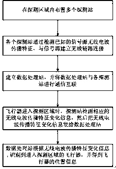
[0029] Such as figure 1 As shown, a method for aircraft detection using passive signals includes the following steps:

[0030] S1. Arrange multiple detection stations in the detection area;

[0031] S2. Each detection station establishes a wireless link connection with the signal source by detecting the radio wave propagation characteristics of the known signal source;

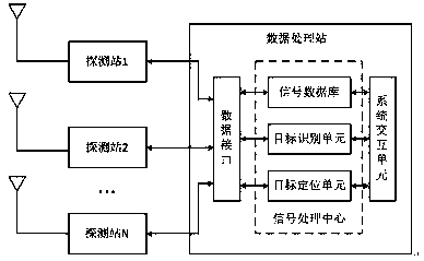
[0032] S3. Establish a data processing station, and communicate and interconnect the data processing station with each detection station;

[0033] S4. When the aircraft enters the detection area, it blocks or reflects the signal transmission between the signal source and the detection station. The detection station detects the corresponding radio wave propagation characteristic change information...


PUM


Abstract

The invention discloses a method and system using passive sourceless signals to carry out aircraft detection; the method comprises the following steps: deploying a plurality of detection stations in adetection area; building a wireless link connection between each detection station and a signal source; building a data processing station, and carrying out communication interconnection between thedata processing station and each detection station; enabling an aircraft to enter the detection area so as to form blocking or reflection on signal transmission between the signal source and the detection stations, wherein the detection station detects corresponding radio wave propagation characteristic change information and sends same to the data processing station; enabling the data processingstation to identify the aircraft that enters the detection area according to the radio wave propagation characteristic change information, and obtaining the aircraft position information. The method can detect the radio wave propagation characteristic changes caused by signal transmission blocking or reflection between the signal source and the detection station after the aircraft enters the detection area, thus identifying and positioning the aircraft in the detection area without using extra frequency spectrum resources; the method and system are simple and accurate in detections.

Description

Technical field [0001] The invention relates to aircraft detection, and in particular to a method and system for aircraft detection using passive signals. Background technique [0002] Unmanned aerial vehicle technology is continuously upgraded and is widely used in various fields to solve many work problems. However, while drones bring convenience to people, they also bring many disadvantages. While drone technology continues to upgrade, drone threats are also escalating. Due to the rapid development of the UAV market, private UAVs can be seen flying in the air everywhere in the market, but most of them are illegal flights and pose a threat to special areas. Therefore, it is necessary to detect aircraft or UAVs. [0003] The detection of aircraft or unmanned aerial vehicles includes active and passive. Passive detection utilizes existing broadcast, mobile communications, television, navigation satellites and other signal sources, does not require additional spectrum resources, an...

Claims


Application Information

Patent Timeline
IPC IPC(8): G01V3/12
CPCG01V3/12
Inventor 邵士海吴飞赵宏志唐友喜
Owner UNIV OF ELECTRONICS SCI & TECH OF CHINA
Learn More