
scroll compressor

A technology of scroll compressors and moving scrolls, applied in the field of scroll compressors, can solve the problems of reduced strength and larger torque of the European ring 100, and achieve the effect of improving installation workability and suppressing the reduction of strength

Inactive Publication Date: 2020-04-24
DAIKIN IND LTD
View PDF2 Cites 0 Cited by
  • Summary
  • Abstract
  • Description
  • Claims
  • Application Information

AI Technical Summary

Problems solved by technology

In addition, since the keys 102 and 103 are formed along the radially outer side of the ring portion 101, there is a problem that the moment acting on the keys 102 and 103 becomes large, and there is also a problem that the strength of the O-ring 100 decreases.

Method used


Image

  • scroll compressor
  • scroll compressor
  • scroll compressor

Examples


Deformed example 1

[0104] Such as Figure 12 As shown, the opposing portion 71 may be formed in a plate shape with a constant thickness. Even with the configuration as described above, the first key groove 61 can be easily formed in the main body portion 23 a of the housing 23 , and the first key 54 can be easily mounted in the first key groove 61 .

Deformed example 2

[0106] Such as Figure 13 As shown, the opposing portion 71 may also be constituted by another member fixed to the main body portion 23 a of the housing 23 . Even with the configuration as described above, the first key groove 61 can be easily formed in the main body portion 23 a of the housing 23 , and the first key 54 can be easily mounted in the first key groove 61 .

Deformed example 3

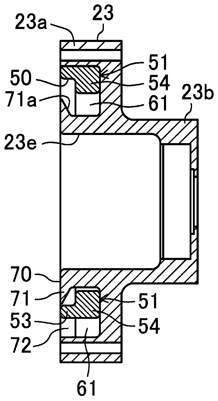
[0108] Such as Figure 14 , Figure 15 As shown, the first key groove 61 may be a groove opened on the outer peripheral surface of the main body portion (flange portion) 23 a of the housing 23 .

[0109] Even with the configuration as described above, the first key groove 61 can be easily formed by a groove opened on the outer peripheral surface of the main body portion (flange portion) 23 a of the housing 23 .


PUM


Abstract

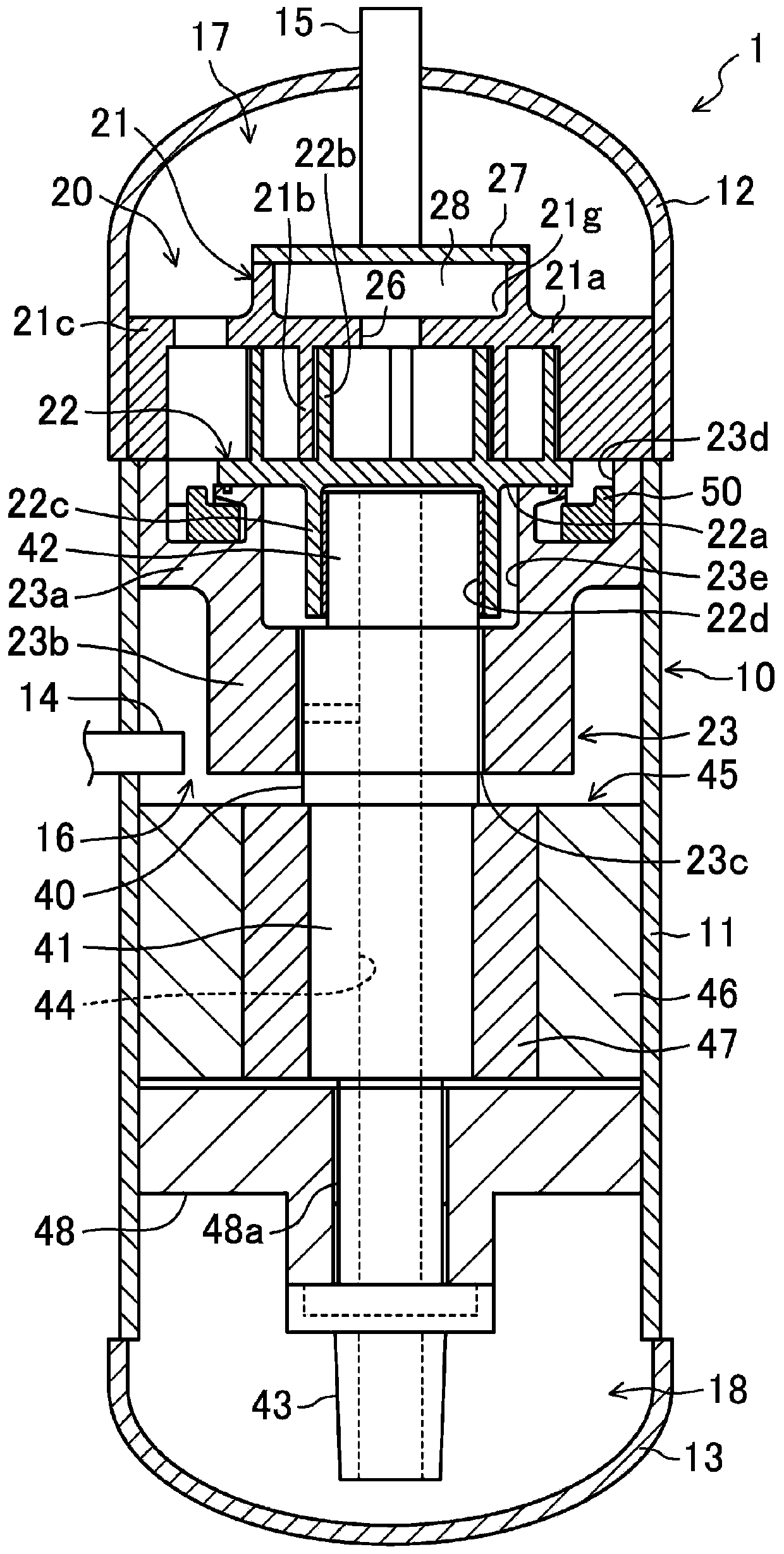
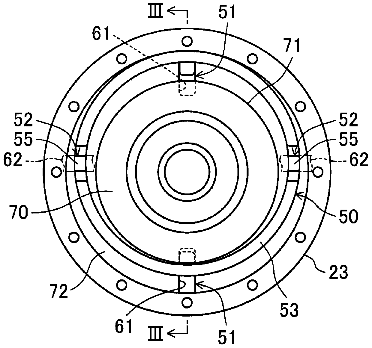
The first key (54) on the housing (23) side of the Euro ring (50) is made to protrude from the ring portion (53) to the housing (23) side and also to the radially inner side. A facing portion (71) having an orbiting scroll facing surface (70) and an annular opening portion (72) for accommodating the ring portion (53) are formed on the flange portion of the casing (23). The first key groove (61) is formed on the back side of the opposing portion (71), and the first key groove (61) is formed from the annular opening portion (72) toward the radially inner side. Thereby, the strength of the casing (23) and the Euclidean ring (50) of the scroll compressor is ensured, and the reduction of the opposing portion (70) of the movable scroll is suppressed.

Description

technical field [0001] The present invention relates to a scroll compressor having a fixed scroll and a movable scroll in a compression mechanism, and particularly relates to a structure of an O-ring which is a rotation prevention mechanism that supports the movable scroll by the compression mechanism. Background technique [0002] In the past, in scroll compressors, such as the top view of the shell and the Euro ring Figure 17 , Its XVIII-XVIII line sectional view is Figure 18 , the top view of the European ring is Figure 19 , its XX-XX line sectional view is Figure 20 As shown, in general, the Oldham ring 100 is used in order to suppress the rotation of the orbiting scroll (not shown) and allow it to revolve. In the Euro ring 100, generally, the ring part 101 and the keys 102 and 103 are integrally formed. In the Euro-style ring 100 , a pair of keys 102 is formed on the surface of the ring portion 101 near the casing 110 , and another pair of keys 103 is formed on t...

Claims


Application Information

Patent Timeline
Patent Type & Authority Patents(China)
IPC IPC(8): F04C18/02
CPCF04C18/02F04C18/0215F01C17/066F16D3/00F16D3/04F04C18/0253F04C2240/30
Inventor 山田壮宏
Owner DAIKIN IND LTD
Learn More