Ejection structure of mold

A mold and ejector plate technology, applied in the field of ejection structure of the mold, can solve problems such as insufficient strength of the oblique pin, difficulty in taking the product by the manipulator, unbalanced ejection, etc., and achieve the effect of avoiding insufficient strength

Active Publication Date: 2020-12-15
SUZHOU MITAC PRECISION TECH
View PDF2 Cites 0 Cited by
  • Summary
  • Abstract
  • Description
  • Claims
  • Application Information

AI Technical Summary

Problems solved by technology

When the product 10 is relatively large and has an undercut 11, if the inclined pin rod used to eject the product 10 is too weak, the strength of the inclined pin is not enough, and the inclined pin is easy to break; if the rod of the inclined pin is made stronger, the ejection imbalance will occur The phenomenon makes it difficult for the manipulator to take the product 10 times, and the automatic production cannot be realized

Method used


Image

  • Ejection structure of mold
  • Ejection structure of mold
  • Ejection structure of mold

Examples


Embodiment Construction

[0021] In order to have a further understanding of the purpose, technical effect and technical means of the present invention, the detailed description is as follows in conjunction with the accompanying drawings.

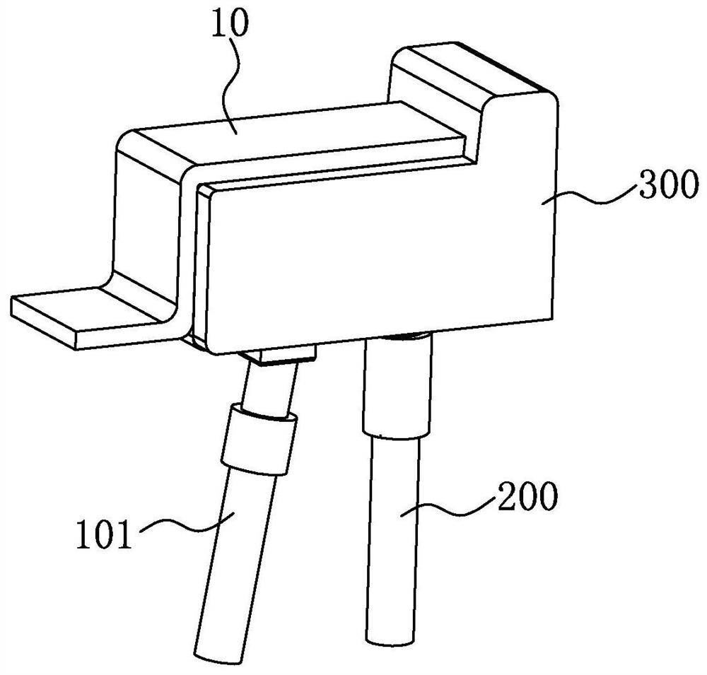
[0022] see Figure 2-5 shown, where figure 2 Illustrated as a three-dimensional schematic view of the ejection structure of the mold of the present invention, image 3 An exploded perspective view showing the ejection structure of the mold of the present invention, Figure 4 Another perspective exploded view showing the ejection structure of the mold of the present invention, Figure 5 Illustrated is a cross-sectional view of the ejection structure of the mold of the present invention.

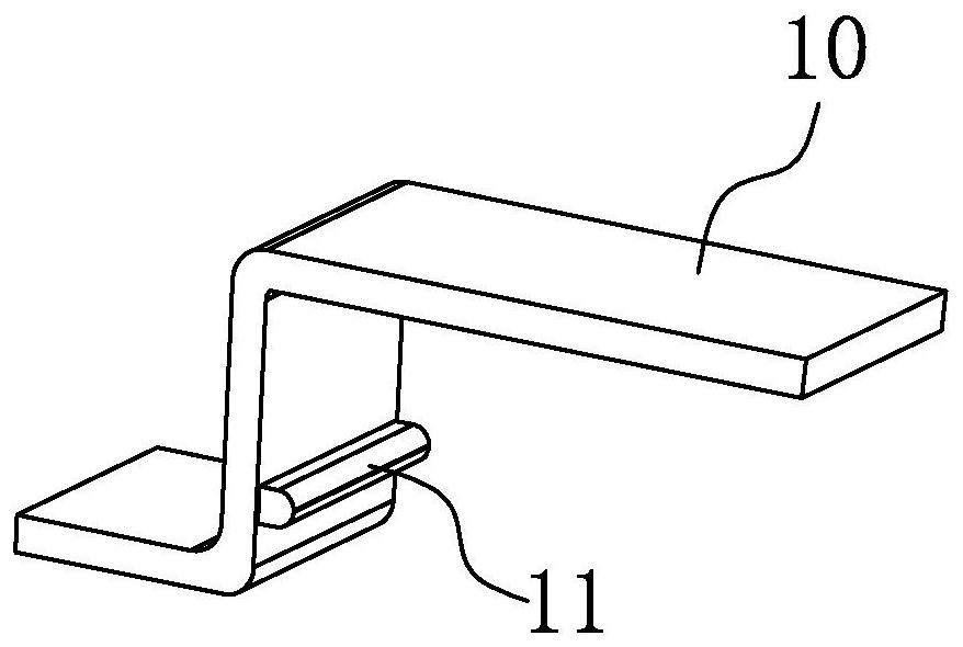
[0023] In this embodiment, the ejection structure of the mold of the present invention is used to eject products 10 with undercuts 11, especially products 10 with larger areas or volumes. The ejection structure of the mold includes:

[0024] Slant pin 100, it has slant pin seat...


PUM


Abstract

The invention provides an ejection structure of a mold . The ejection structure of the mold ejects a product provided with an inverted buckle, and comprises an angle pin, an ejector rod and a direct push block, wherein the angle pin is provided with an angle pin seat, an angle pin rod and an angle pin head, the angle pin seat is fixed in an ejection plate of the mold, one end of the angle pin rodis movably arranged in the angle pin seat, and the angle pin head forms the inverted buckle of the product; one end of the ejector rod is fixed in the ejection plate of the mold; and the other end ofthe ejector rod abuts against the direct push block, the direct push block abuts against the product, a groove is formed in the direct push block, the angle pin head of the angle pin is arranged in the groove, and a space is reserved between the groove and the angle pin head of the angle pin, so that the angle pin can retreat. According to the ejection structure of the mold, the direct push blockdecomposes the ejection pressure of the angle pin, the insufficient strength of the angle pin is avoided, ejection balance is achieved, and therefore, the product with the inverted buckle can be smoothly ejected.

Description

【Technical field】 [0001] The invention relates to the technical field of injection molds, in particular to a mold ejection structure. 【Background technique】 [0002] When injection molding plastic products, the product will have an undercut due to functional requirements, and an oblique pin needs to be used to withdraw from the undercut. [0003] However, see figure 1 As shown, it depicts a schematic diagram of a product with an undercut. When the product 10 is relatively large and has an undercut 11, if the inclined pin rod used to eject the product 10 is too weak, the strength of the inclined pin is not enough, and the inclined pin is easy to break; if the rod of the inclined pin is made stronger, the ejection imbalance will occur This phenomenon makes it difficult for the manipulator to take the product 10, and cannot realize automatic production. [0004] In view of this, it is necessary to develop a mold ejection structure to solve the above problems. 【Content of i...

Claims


Application Information

Patent Timeline
Patent Type & Authority Applications(China)
IPC IPC(8): B29C45/40B29C45/44
CPCB29C45/4005B29C45/44B29C2045/445
Inventor 吴建兵
Owner SUZHOU MITAC PRECISION TECH
Why Eureka
Try Eureka