Jet regulator that can be pivoted into a cleaning position

A technology of jet flow regulator and cleaning position, which is applied to water supply devices, indoor sanitary piping devices, buildings, etc., can solve the problems of jet flow regulator cleaning being unfeasible and not being provided.

Active Publication Date: 2018-08-03
NEOPERL
View PDF9 Cites 0 Cited by
  • Summary
  • Abstract
  • Description
  • Claims
  • Application Information

AI Technical Summary

Problems solved by technology

Since the joint sleeve abuts already at a relatively small pivot angle on the component of the known jet regulator arranged upstream on the inflow side, which also serves as a pivot stop, the known Cleaning of the jet regulator is neither possible nor provided in the installed state

Method used


Image

  • Jet regulator that can be pivoted into a cleaning position
  • Jet regulator that can be pivoted into a cleaning position
  • Jet regulator that can be pivoted into a cleaning position

Examples


Embodiment Construction

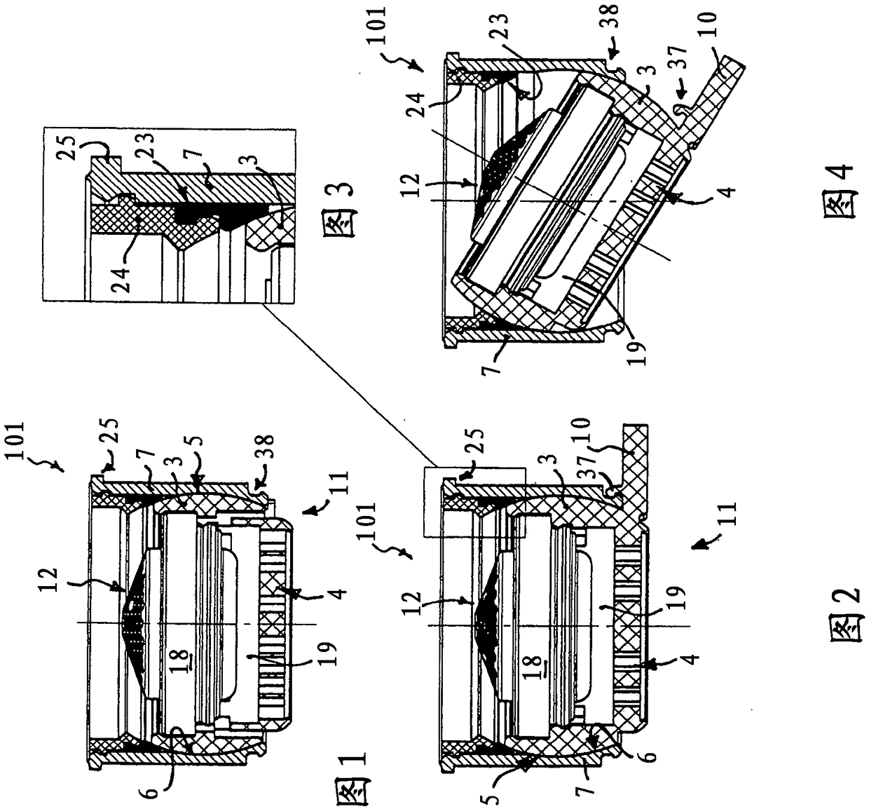
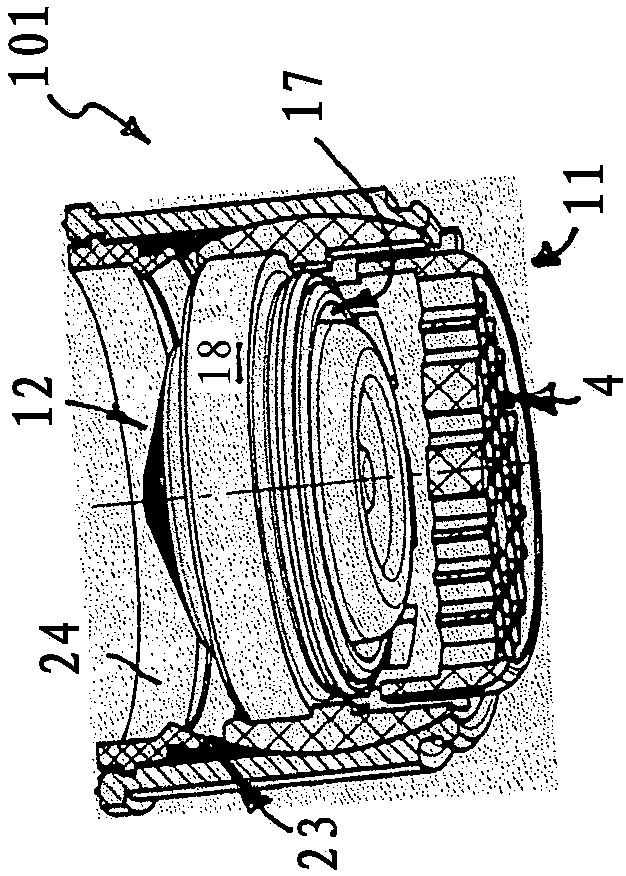
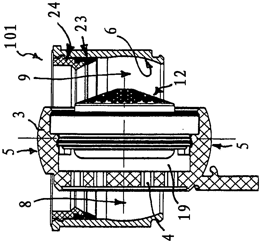
[0093] exist Figures 1 to 41 Seven embodiments 101 , 102 , 103 , 104 , 105 , 106 , 107 of jet regulators are shown in FIG. as in Figure 7 As exemplarily shown in , the jet regulator embodiments 101, 102, 103, 104, 105, 106 and 107 can be mounted on the outlet 1 of the sanitary outlet fitting 2 in order to create a uniform and splash-free jet there. water jet. The jet regulators 101 , 102 , 103 , 104 , 105 , 106 and 107 shown here each have a wall 3 with a wall forming the jet regulators 101 , 102 , 103 , 104 , 105 , 106 and 107 . Pore ​​structure 4 on the outlet end side. The wall part 3 , which is designed here as a joint or pivoting sleeve and is designed as an annular wall part, is mounted pivotably by means of its ball-table-shaped outer circumference 5 in the joint socket 6 which is arranged in the jet control On the inner peripheral wall of the housing of the device housing 7. The wall part 3 is pivotably mounted in the glenoid socket 6 by means of its ball-table-...


PUM


Abstract

The invention relates to a jet regulator (101), comprising a tubular jet regulator housing (7), which can be mounted on the water outlet of a sanitary outlet fitting, and comprising a wall (3), whichbears a hole structure (4) forming the outlet end face of the jet regulator (101) and which can be pivoted in the jet regulator housing (7) between a usage position, in which the hole structure (4) extends transversely over an outlet-side tube opening of the jet regulator housing (7), and a cleaning position, in which the water flowing through the jet regulator housing (7) can flow out of the jetregulator housing (7) on both sides of the wall (3) through opening gaps (8, 9) formed between the wall (3) and the adjacent housing inner peripheral wall. The jet regulator (101) according to the invention is characterized in that the wall (3) has a spherical-segment-shaped outer periphery (5) and is pivotably supported in a joint socket (6) by means of said spherical-segment-shaped outer periphery (5), which joint socket is provided on the housing inner peripheral wall of the jet regulator housing (7).

Description

technical field [0001] The invention relates to a jet regulator, which has a sleeve-shaped jet regulator housing that can be installed at the water outlet of a sanitary outlet fitting, and a wall that forms a jet regulator The hole structure on the outlet end side of the device, and the wall part is pivotable in the jet regulator housing between the use position and the cleaning position, in which the hole structure is transversely in the jet regulator housing Extending over the housing opening on the outflow side of the nozzle, water flowing through the jet regulator housing in the cleaning position can flow from the jet through at least one opening gap formed between the wall part and the adjacent inner peripheral wall of the housing. out of the regulator housing. Background technique [0002] A jet regulator of the type mentioned at the outset is known from WO 2014 / 142766 A1. This known jet regulator has a sleeve-shaped jet regulator housing which can be mounted on the ...

Claims


Application Information

Patent Timeline
Patent Type & Authority Applications(China)
IPC IPC(8): E03C1/086
CPCE03C1/086E03C1/084E03C2001/082
Inventor G·布卢姆
Owner NEOPERL
Why Eureka
Try Eureka