


Quick Research
Generate reliable direction feasibility study reports for your R&D in just a few steps.

Technical Q&A
Discover and master advanced knowledge NOW. Basics, ideas, possibilities, all at once.

Find Solutions
As an expert in R&D theories, this can generate solutions to your technical problems instantly.

Evaluate Feasibility
Analyze your overall solution with one click, know your potential R&D risks in advance.

Monitor Landscape
Get weekly tech updates, stay abreast of the latest tech innovations and key insights.
Ammonia removal equipment, ammonia removal method, and hydrogen gas production method
A kind of equipment and ammonia gas technology, which is applied in the field of ammonia removal equipment, can solve the problems such as the adverse effect of the catalyst layer, and achieve the effect of reducing the frequency of replacement or regeneration
- Summary
- Abstract
- Description
- Claims
- Application Information
AI Technical Summary
Problems solved by technology
Method used
Image

Examples
no. 1 Embodiment approach
[0068] Next, the ammonia removal facility and the ammonia removal method according to this embodiment will be described with reference to the drawings.
[0069]
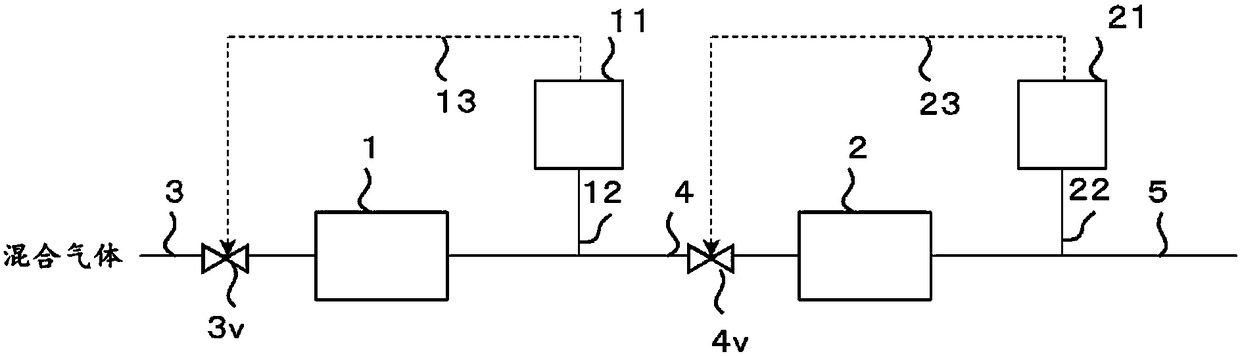
[0070] figure 1 It is a schematic diagram of the ammonia removal facility concerning 1st Embodiment.
[0071] The ammonia removal facility according to the first embodiment has a first ammonia removal device 1, is arranged in the rear stage of the first ammonia removal device 1, and processes the first process gas treated by the first ammonia removal device 1. The second ammonia removal device 2, the first ammonia concentration measuring device 11 for measuring the ammonia concentration in the first treated gas treated by the first ammonia removal device 1, and the first ammonia concentration measurement device 11 for measuring the ammonia concentration by the second ammonia removal device 2 A second ammonia concentration measuring device 21 for the ammonia gas concentration in the processed second processing gas....
no. 2 Embodiment approach
[0156]
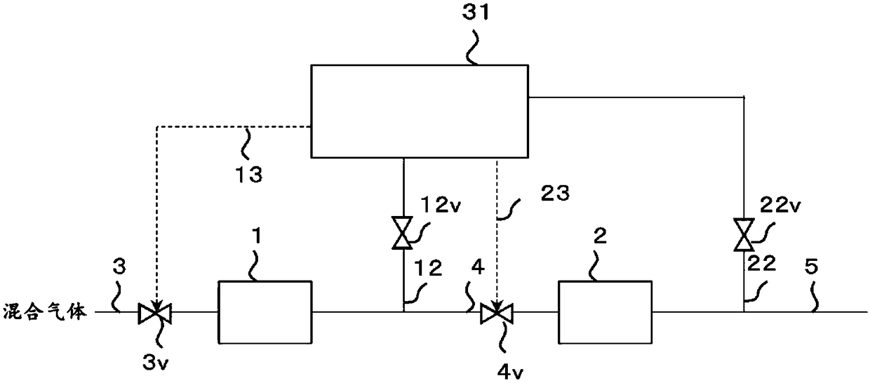
[0157] figure 2 It is a schematic diagram of the ammonia removal facility concerning 2nd Embodiment.
[0158] The ammonia removal facility according to the second embodiment has a first ammonia removal device 1, is installed in the rear stage of the first ammonia removal device 1, and processes the first process gas treated by the first ammonia removal device 1. The 2nd ammonia removal device 2, and the ammonia gas concentration in the 1st process gas that can be processed by the 1st ammonia removal device 1 and the ammonia concentration in the 2nd process gas that is processed by the 2nd ammonia removal device 2 The first ammonia concentration measuring device 31 of the ammonia gas concentration.
[0159] The piping 3 provided with the on-off valve 3v is connected to the inflow port of the said 1st ammonia removal apparatus 1. The outlet of the first ammonia removal device 1 and the inlet of the second ammonia removal device 2 are connected via a pipe 4 provided...
no. 3 Embodiment approach
[0179]
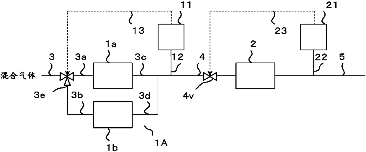
[0180] image 3 It is a schematic diagram of the ammonia removal facility concerning 3rd Embodiment.
[0181] In this ammonia removal facility, in the ammonia removal facility according to the first embodiment, instead of the first ammonia removal device 1 and the on-off valve 3v, a plurality of (two in this embodiment) first ammonia removal containers installed in parallel are used. The first ammonia removal device 1A of 1a, 1b and the three-way valve 3e are the same as the ammonia removal facility according to the first embodiment.
[0182] In addition, the same code|symbol as the ammonia removal facility which concerns on 1st Embodiment shows the same part.
[0183] Specifically, the first ammonia removal device 1A has two first ammonia removal containers 1a, 1b installed in parallel, is divided into two from the rear stage of the piping 3, and is connected to the flow of the two first ammonia removal containers 1a, 1b. Two pipes 3a, 3b connected to the inlet, ...
PUM
| Property | Measurement | Unit |
|---|---|---|
| pore size | aaaaa | aaaaa |
| pore size | aaaaa | aaaaa |
| pore size | aaaaa | aaaaa |
Abstract
Description
Claims
Application Information
 - R&D Engineer
- R&D Manager
- IP Professional
- Industry Leading Data Capabilities
- Powerful AI technology
- Patent DNA Extraction
Browse by: Latest US Patents, China's latest patents, Technical Efficacy Thesaurus, Application Domain, Technology Topic, Popular Technical Reports.
© 2024 PatSnap. All rights reserved.Legal|Privacy policy|Modern Slavery Act Transparency Statement|Sitemap|About US| Contact US: help@patsnap.com