
Fixing apparatus in which a fixing nip is secured by a pressure belt and a fixing roller, and image formation apparatus that includes the fixing apparatus

a technology of fixing rollers and fixing nips, which is applied in the direction of electrographic process apparatus, instruments, optics, etc., can solve the problems of increasing labor time and cost, and achieve the effects of reducing the frequency of replacing the belt, reducing the pressure in the area, and reducing the erosion of the bel

Inactive Publication Date: 2009-02-26
KONICA MINOLTA BUSINESS TECH INC
View PDF5 Cites 19 Cited by
  • Summary
  • Abstract
  • Description
  • Claims
  • Application Information

AI Technical Summary

Benefits of technology

[0010]However, performing frequent replacement leads to a commensurate increase in labor time and cost.
[0011]The present invention has been achieved in view of the above problem, and an aim thereof is to provide a fixing apparatus that can reduce the frequency of replacement of the pressure belt, etc. while preventing image slippage, and an image formation apparatus including the fixing apparatus.

Problems solved by technology

However, performing frequent replacement leads to a commensurate increase in labor time and cost.

Method used


Image

  • Fixing apparatus in which a fixing nip is secured by a pressure belt and a fixing roller, and image formation apparatus that includes the fixing apparatus
  • Fixing apparatus in which a fixing nip is secured by a pressure belt and a fixing roller, and image formation apparatus that includes the fixing apparatus
  • Fixing apparatus in which a fixing nip is secured by a pressure belt and a fixing roller, and image formation apparatus that includes the fixing apparatus

Examples


Embodiment Construction

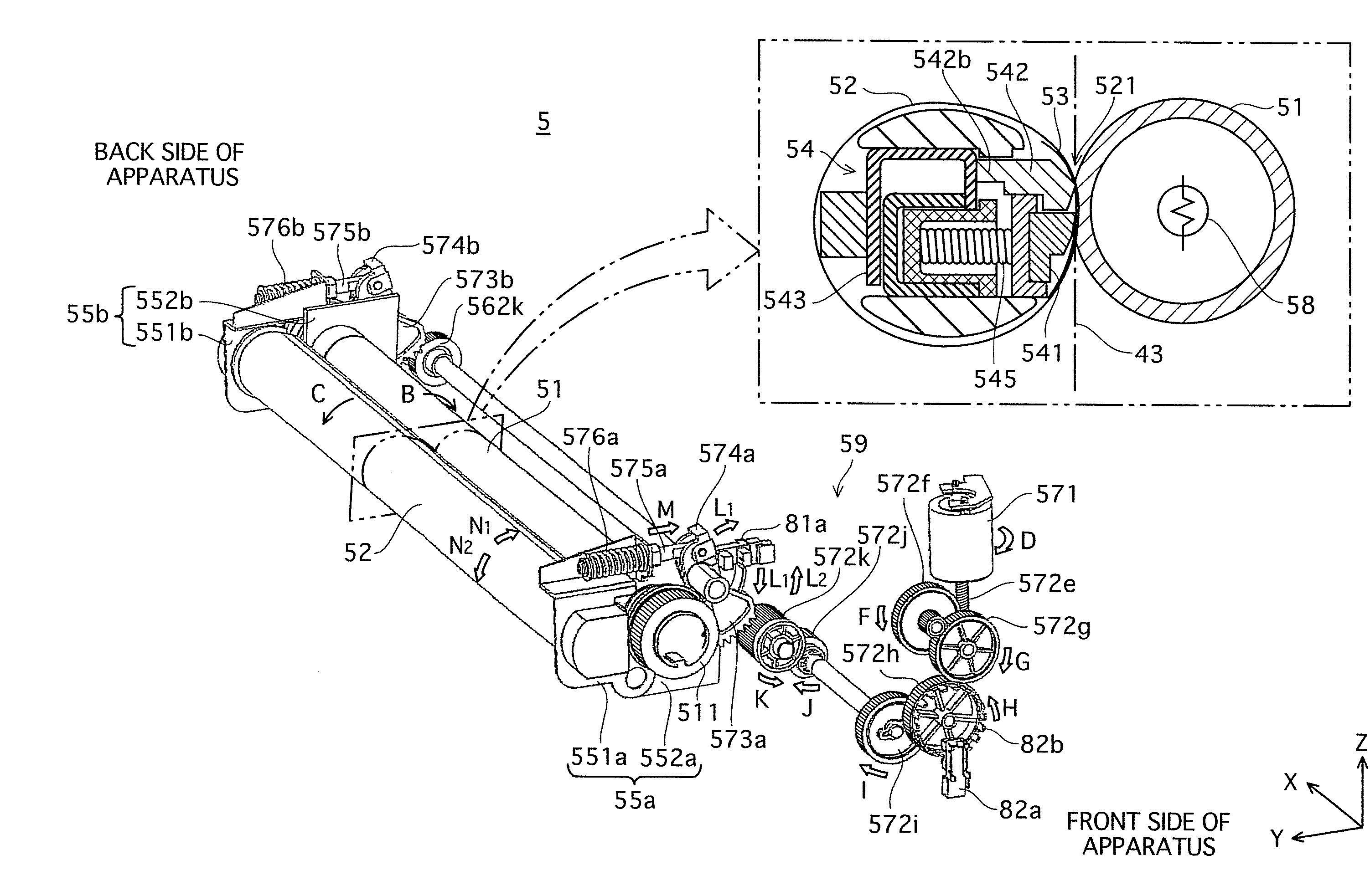
[0033]The following describes a tandem-type color digital printer (hereinafter, referred to simply as a “printer”) as an example of the fixing apparatus of the present invention. Note that although the printer embodying the technological idea of the present invention is given as an example in the following embodiment, the present invention is not limited to this.

[0034]Printer Structure

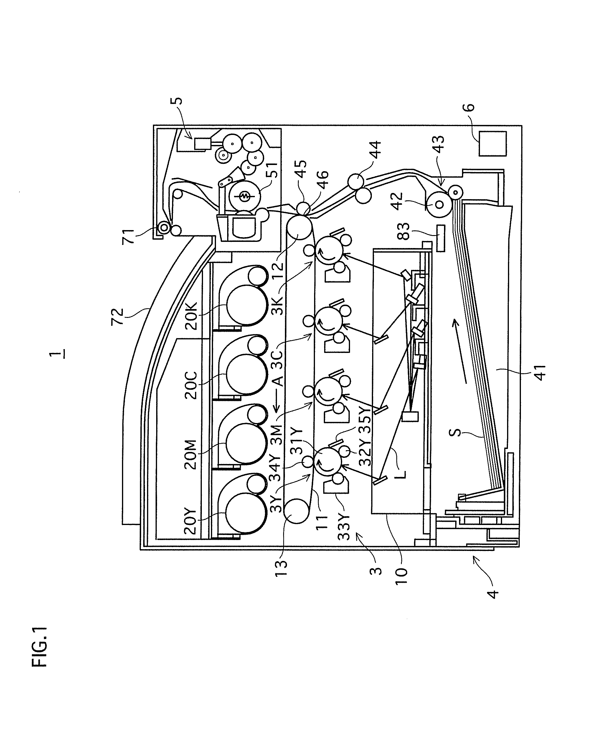
[0035]FIG. 1 is a schematic sectional view showing a structure of a printer 1 pertaining to the present embodiment.

[0036]As shown in FIG. 1, the printer 1 includes an image processor 3, a feeder 4, a fixer 5, and a controller 6. The printer 1 is connected to a network such as a LAN, and upon receiving a print job execution instruction from an external terminal apparatus (not depicted), executes color image formation in accordance with the instruction, the color image being composed of colors yellow, magenta, cyan, and black. The yellow, magenta, cyan and black reproduction colors are hereinafter repres...


PUM


Abstract

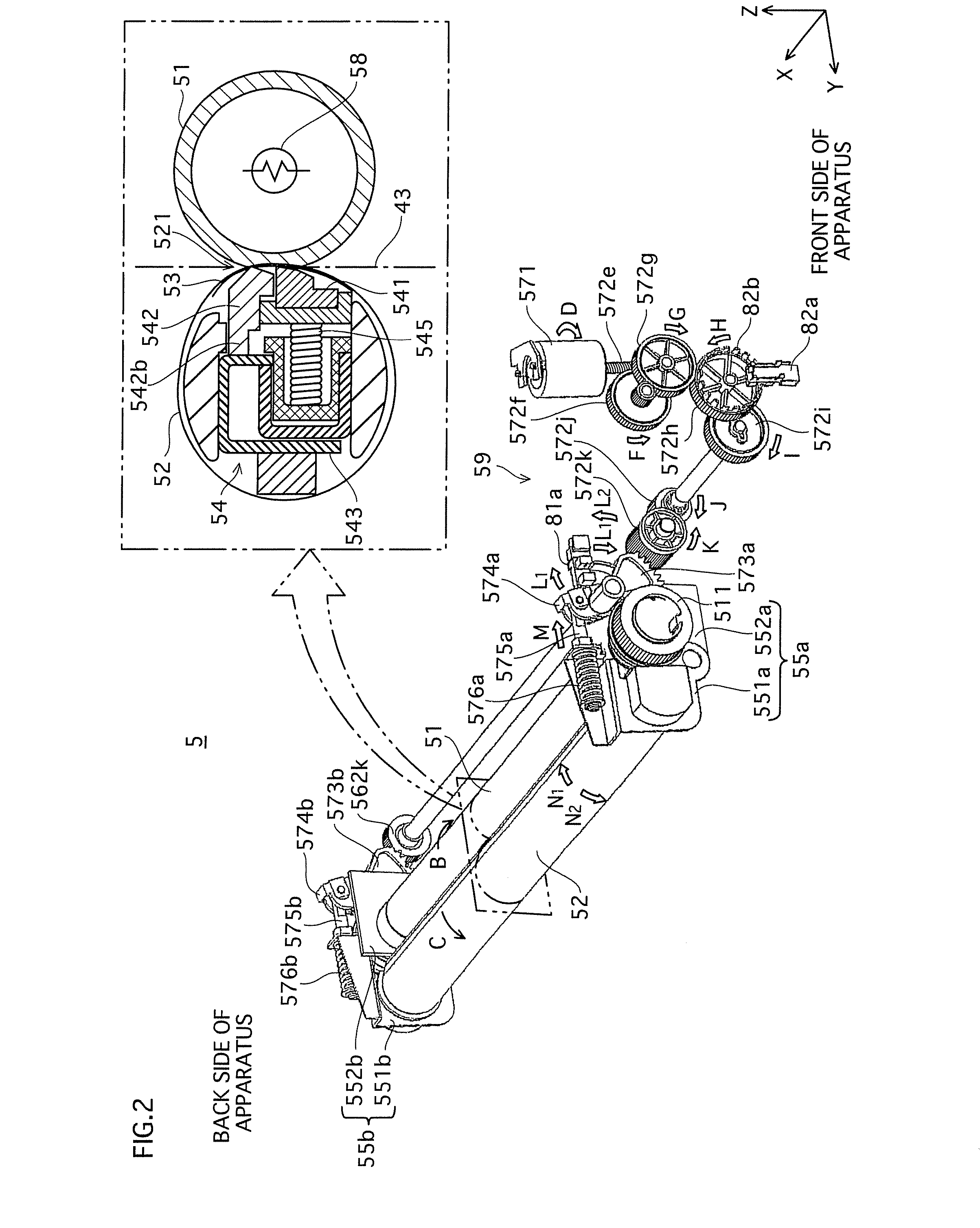
A belt-nip system fixing apparatus or an image formation apparatus including the fixing apparatus reduces the frequency of replacing a pressure belt or a sliding sheet. In accordance with a sheet measurement in a roller axis direction, the fixing apparatus or image formation apparatus switches a pressure distribution in the roller axis direction between a low-pressure load distribution in which pressure is greatest at a center pressure switching projection (542b) of a hard pad (542), and pressure gradually lessens towards pressure switching projections (543c) near the ends of the hard pad (542), and the pressure in a range of 216 [mm] in a center in the roller axis direction is greater than or equal to a necessary pressure for fixing (a predetermined value Nm) while the pressure in other projections near the ends is below the predetermined value Nm, and a high-pressure load distribution in which the pressure throughout the total area in the roller axis direction equals or exceeds the predetermined value Nm.

Description

[0001]This application is based on application No.2007-214635 filed in Japan, the content of which is hereby incorporated by reference.BACKGROUND OF THE INVENTION[0002]1. Field of the Invention[0003]The present invention relates to a fixing apparatus that fixes an unfixed image on a recording sheet by passing the recording sheet through a fixing nip, and an image formation apparatus that includes the fixing apparatus.[0004]2. Related Art[0005]In fixing apparatuses included in image formation apparatuses such as copiers, there is a so-called belt-nip system in which a fixing nip is secured by pressing a pressure belt against a fixing roller, and an unfixed image formed from toner or the like on a recording sheet is fixed thereon by passing the recording sheet between the pressure belt and the fixing roller (see Japanese Patent Application Publication No. 2005-300732).[0006]In a belt-nip system fixing apparatus, a pressing member that presses the pressure belt towards the fixing rolle...

Claims


Application Information

Patent Timeline
Patent Type & Authority Applications(United States)
IPC IPC(8): G03G15/20
CPCG03G2215/00734G03G15/206G03G2215/2009
Inventor FUJIMOTO, YOSHIHISA
Owner KONICA MINOLTA BUSINESS TECH INC
Learn More