
Microstrip line proximal couple feeding-based multi-frequency-band antenna

A multi-band antenna and coupled feeding technology, which is applied to antennas, antenna grounding devices, and devices that enable antennas to work in different bands at the same time, can solve the problem that the antenna does not meet the antenna simulation results, the antenna reduces the antenna efficiency, and increases the difficulty of antenna debugging and other problems, to achieve the effect of easy design, installation and debugging, miniaturization design and simple structure

Active Publication Date: 2018-08-03
HARBIN ENG UNIV
View PDF2 Cites 4 Cited by
  • Summary
  • Abstract
  • Description
  • Claims
  • Application Information

AI Technical Summary

Problems solved by technology

[0003] At this stage, the existing multi-frequency antennas have WLAN antennas with asymmetric coplanar feeds, but the reactance usually loaded on the antennas reduces the efficiency of the antennas.
There are also monopole antennas with asymmetric coplanar feed, but the mutual influence between each monopole antenna increases the difficulty of antenna debugging
There are also multi-band antennas that use coaxial feed, which will increase additional inductance, so that the actual antenna does not meet the simulation results of the antenna, and increases the space size of the antenna. These are not suitable for modern antennas. Miniaturization, many Functional, miniaturized design concept

Method used


Image

  • Microstrip line proximal couple feeding-based multi-frequency-band antenna
  • Microstrip line proximal couple feeding-based multi-frequency-band antenna
  • Microstrip line proximal couple feeding-based multi-frequency-band antenna

Examples


Embodiment Construction

[0017] Below in conjunction with accompanying drawing, the present invention is described in detail as follows:

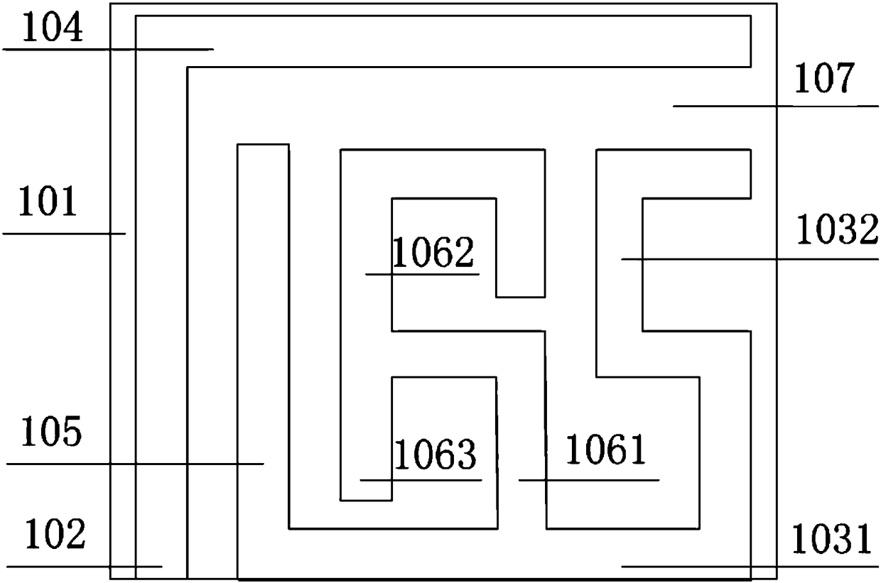
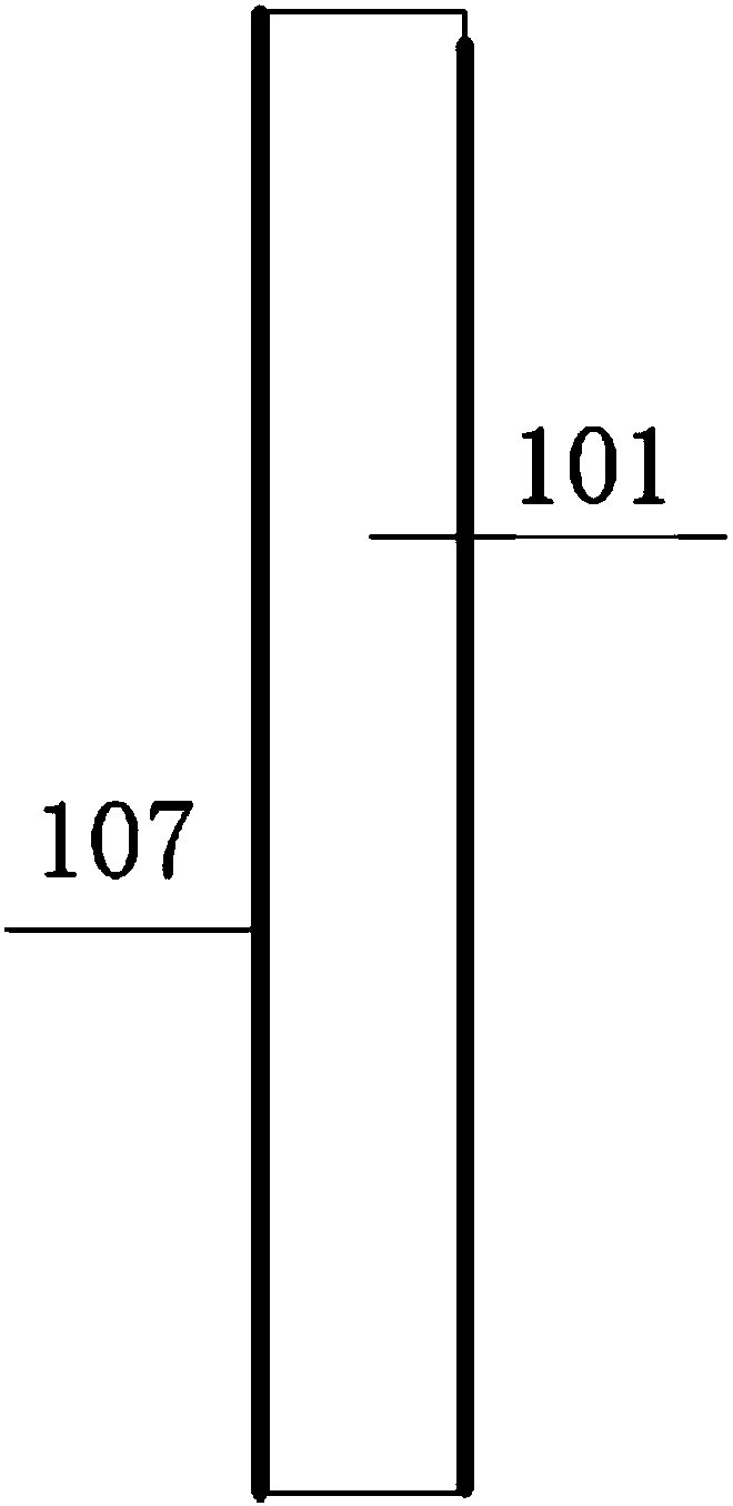
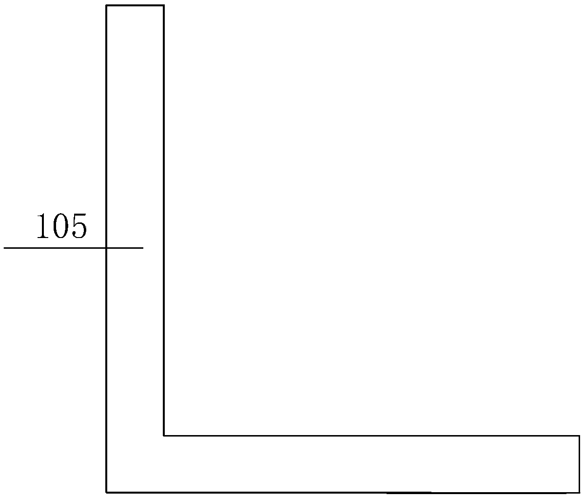
[0018] The object of the present invention is achieved in this way: the antenna mainly includes a dielectric substrate 101, a microstrip line adjacent to a coupling feed structure, an L-shaped monopole radiation unit 105, an inverted L-shaped radiation unit 1063 loaded, and a bent radiation unit 1062 and S-shaped radiating elements. The L-shaped monopole radiating unit 105, the loaded inverted L-shaped radiating unit 1063, the bent-shaped radiating unit 1062, and the S-shaped radiating unit form a series adjacent coupling feeding mechanism, and the designed adjacent coupling feeding mechanism consists of an L-shaped The microstrip transmission line and the ground plane 107 are composed. The loaded inverted L-shaped radiating unit 1063 and the bent-shaped radiating unit 1062 adopt a common feed transmission structure, and the two resonant frequencies can be adjuste...


PUM


Abstract

The invention discloses a microstrip line proximal couple feeding-based multi-frequency-band antenna, and belongs to the technical field of communication. By adopting a microstrip line proximal couplefeeding structure and radiation unit series method, design of the multi-frequency-band antenna is realized; and the antenna mainly comprises a dielectric substrate 101, a microstrip line proximal couple feeding structure, an L-shaped monopole radiation unit 105, an inverted L-shaped radiation unit 1063, a bent radiation unit 1062 and an S-shaped radiation unit. By virtue of the distance between the microstrip line feeder line with the microstrip line proximal couple feeding structure and the radiation units, and the dimensions of the four radiation units, the wireless communication requirement of a multi-frequency-band indoor base station can be satisfied. The microstrip line proximal couple feeding-based multi-frequency-band antenna disclosed in the invention is reasonable in layout, simple in design, easy to integrate, convenient to debug and wide in application field.

Description

technical field [0001] The invention belongs to the technical field of communication, and in particular relates to a multi-band antenna based on microstrip line proximity coupling feeding. Background technique [0002] The antenna is a key component of the communication system. It is a device that can convert the transmitted guided wave into a free space wave. The superiority of the performance of the antenna directly determines the quality of the communication system. In recent years, the rapid development of wireless communication technology, the current 3G, 4G and future 5G communication, access technology also appeared WLAN, WIMAX, etc., all kinds of wireless communication equipment have been deeply integrated into people's work and life , and the frequency band occupied by each wireless network is gradually increasing, and with the development of miniaturization and diversification of wireless communication equipment, various communication systems continue to emerge. D...

Claims


Application Information

Patent Timeline
Patent Type & Authority Applications(China)
IPC IPC(8): H01Q1/38H01Q1/48H01Q5/50
CPCH01Q1/38H01Q1/48H01Q5/50
Inventor 李迎松罗生元董玥
Owner HARBIN ENG UNIV
Learn More