6PIN dual-interface chip smart card and preparation method thereof
A 6PIN, dual-interface technology, applied in the field of smart cards, to achieve the effects of reduced area, increased design space, and improved reliability
- Summary
- Abstract
- Description
- Claims
- Application Information
AI Technical Summary
Problems solved by technology
Method used
Image
Examples
Embodiment 1
[0031] The 6PIN dual interface chip smart card of the present invention includes a 6PIN dual interface chip module, a card body, and a winding antenna. The wire-wound antenna is used to realize the welding connection between the card body and the 6PIN dual interface chip module.
[0032] As an example, the size of the 6PIN dual interface chip module of the 6PIN dual interface chip smart card provided by the present invention is 8.0mm*10.62mm, and the distance between two non-contact contacts is 10.52mm.
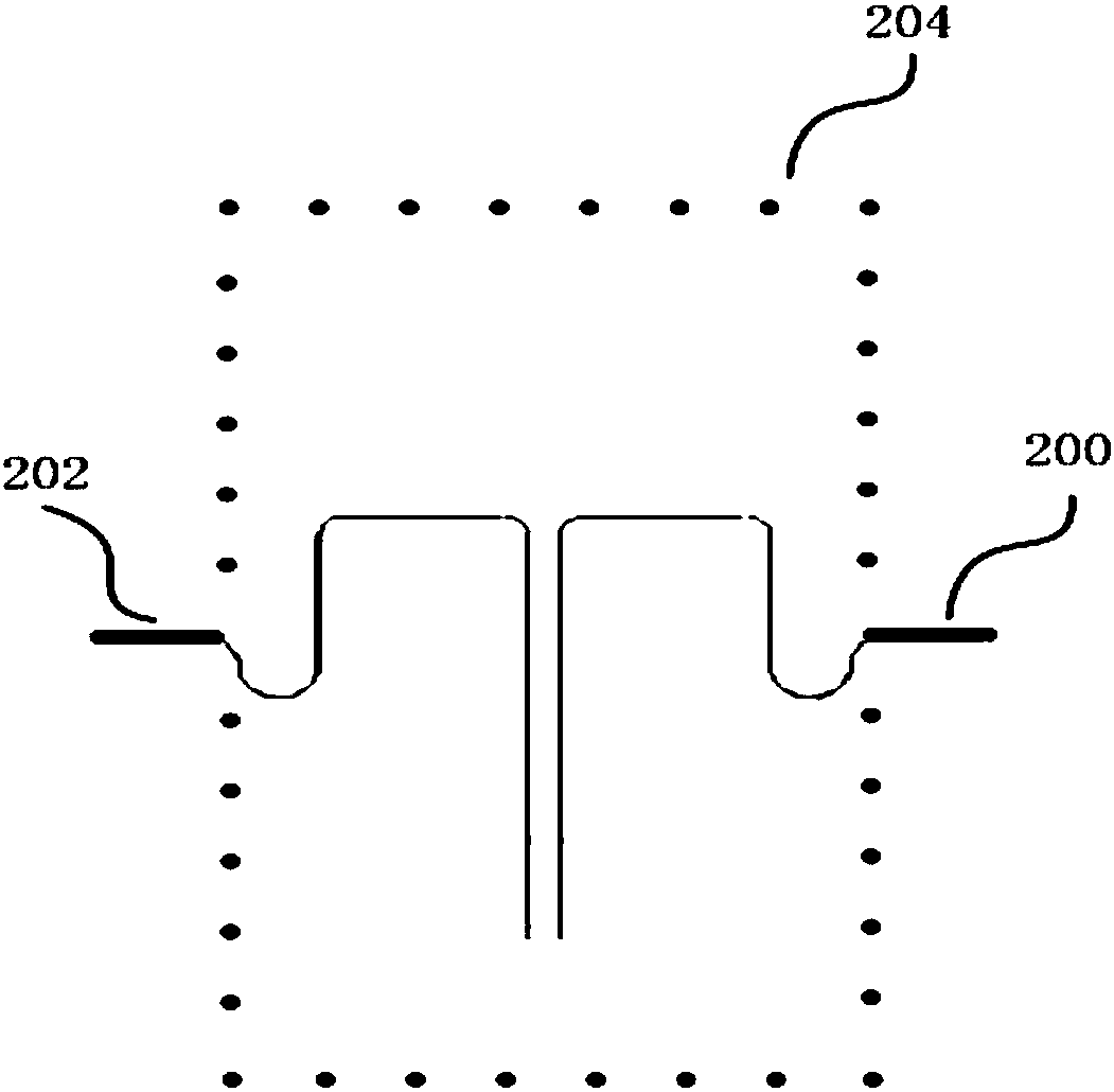
[0033] As a better choice, the winding antenna has an M-type winding head (see figure 2 ), and the winding head and tail are lengthened. Specifically, the length of the head (200) and the tail (202) of the winding antenna outside the chip area (204) are both 10mm-11mm. As the distance between the two non-contact contacts of the 6PIN dual interface module is reduced, the existing antenna coil cannot be coupled to communicate with it. When the M-type winding head is used and the wi...
Embodiment 2
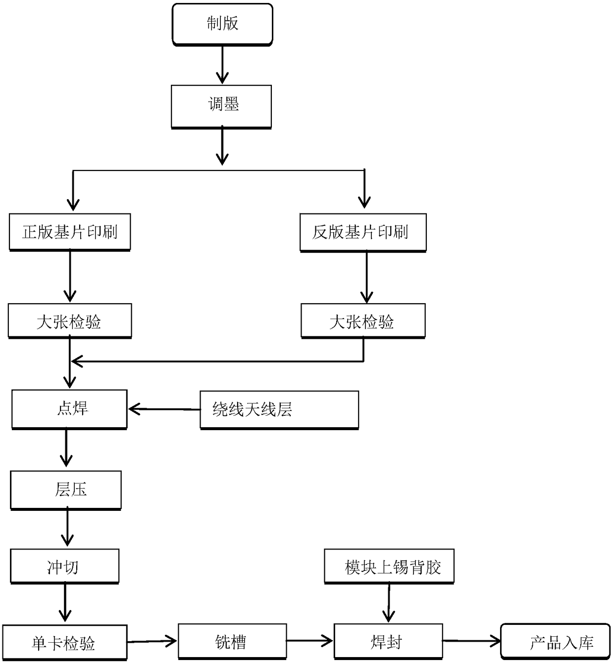
[0038] The 6PIN dual interface chip smart card of the present invention includes a 6PIN dual interface chip module, a card body, and a winding antenna. Correspondingly, a method for preparing a 6PIN dual-interface chip smart card includes the following steps:
[0039] 1. Prepare the card base
[0040] See attached figure 1 , The steps of preparing the card base include plate making and ink adjustment steps, and printing and preparing the genuine substrate and the reverse substrate according to the conventional steps, and then enter the next process after passing the inspection.
[0041] 2. Provide intermediate card base material
[0042] Provide the middle substrate layer of the built-in wire-wound antenna, the wire-wound antenna has an M-type wire head; the length of the head and tail of the wire-wound antenna outside the chip area are both 10mm-11mm. The wire-wound antenna is used to realize the welding connection between the card body and the 6PIN dual interface chip module. It s...
Embodiment 3
[0063] A method for preparing a 6PIN dual interface chip includes the following steps:
[0064] 1. Prepare the card base
[0065] See Example 2.
[0066] 2. Provide intermediate card base material
[0067] Provide an intermediate card base material sheet with a built-in wire-wound antenna, the wire-wound antenna having an M-type winding head.
[0068] See figure 2 The M-type winding head of the winding antenna includes windings arranged mirror-symmetrically with a pitch of 0.4mm. For a single winding, it can further include various winding methods, and the specific shape can be It can be adjusted in any desired manner; the length of the head and tail of the M-type winding head outside the chip area is 11 mm.
[0069] 3. Spot welding steps
[0070] Perform spot welding alignment of the middle substrate layer with the wire-wound antenna coil with the original substrate and the reverse substrate, and then perform spot welding alignment on the protective film of the original substrate and t...
PUM
 Abstract
Description
Claims
Application Information
 - R&D
- Intellectual Property
- Life Sciences
- Materials
- Tech Scout
- Unparalleled Data Quality
- Higher Quality Content
- 60% Fewer Hallucinations
Browse by: Latest US Patents, China's latest patents, Technical Efficacy Thesaurus, Application Domain, Technology Topic, Popular Technical Reports.
© 2025 PatSnap. All rights reserved.Legal|Privacy policy|Modern Slavery Act Transparency Statement|Sitemap|About US| Contact US: help@patsnap.com


