
Building structure provided with temperature control device

A technology for temperature control device and building structure, which is applied in construction, sustainable building, infrastructure engineering, etc., can solve problems such as waste, and achieve the effect of maintaining the balance of the underground temperature field, improving work efficiency, and preventing cracks

Active Publication Date: 2018-08-03
YANCHENG INST OF TECH
View PDF7 Cites 4 Cited by
  • Summary
  • Abstract
  • Description
  • Claims
  • Application Information

AI Technical Summary

Problems solved by technology

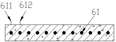
[0003] Prior to the present invention, Chinese patents "a large-volume concrete water-cooled pipeline system" (CN204662991U), "a built-in circulating water pipe for reducing the hydration heat of large-volume concrete" (CN204983667U), "based on mass concrete cooling System" (CN205502594U), etc., have proposed a series of high-efficiency mass concrete cooling measures to reduce energy consumption and conform to the concept of green ecology and environmental protection. However, after the mass concrete cooling construction is completed, the embedded water pipes will remain In concrete, causing great waste

Method used


Image

  • Building structure provided with temperature control device
  • Building structure provided with temperature control device
  • Building structure provided with temperature control device

Examples


Embodiment Construction

[0022] The specific embodiments of the present invention will be further described below in conjunction with the accompanying drawings and examples. The solution of the present invention includes but is not limited to the description of this embodiment.

[0023] The basement floor of a building is 21m long, 18m wide, and 1.5m thick. The construction period is July, and there is no river nearby. The present invention divides the whole base plate into four areas, each area is 10.5m long and 9m wide, each area adopts the same operation, and the specific steps are as follows:

[0024] 1. Set out the line and determine the pipeline layout route.

[0025] 2. Pre-embed the water delivery pipe at the vertical center of the foundation floor. The φ48mm galvanized pipe with a length of 6m / section is formed by connecting several "U"-shaped pipes end to end, and the water delivery pipe and the joint are welded. The distance between the water delivery pipes is 0.8m, the first pipe is 0.5m...


PUM


Abstract

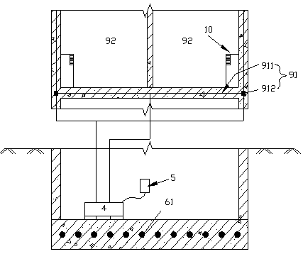
The invention discloses a building structure provided with a temperature control device. The building structure comprises a concrete foundation and an upper structure on the concrete foundation, wherein an upper structure terrestrial heat exchanging system is arranged in the upper structure; the building structure further comprises a water pipeline and the temperature control device connected withthe water pipeline; the water pipeline is formed by connecting water pipes horizontally paved in the concrete foundation end to end; the temperature control device comprises a water tank, a water pump, a reversing valve and a controller; the reversing valve has a first communicating state and a second communicating state; when the reversing valve is in the first communicating state, cooling wateris introduced in the water pipeline; and when the reversing valve is in the second communicating state, the water pipeline is used for heating and cooling the upper structure after the building structure is constructed. The building structure overcomes the defects that the horizontal type ground-source heat pump system occupies a large area, a vertical type ground-source heat pump system is difficult in construction, and the pile bearing capacity is influenced by a certain extent, improves the working efficiency of the ground-source heat pump system and creates healthy and comfortable workingand living environments.

Description

technical field [0001] The invention relates to the technical field of large volume cooling and building energy saving, in particular to a building structure with a temperature control device. Background technique [0002] my country's "Code for Construction of Mass Concrete" GB50496-2009 stipulates that the minimum geometric size of the concrete structure is not less than 1m, or it is expected to cause harmful cracks due to temperature changes and shrinkage caused by the hydration of the cementitious material in the concrete. The resulting concrete is called mass concrete. Modern buildings often involve large-volume concrete construction, such as high-rise building foundations, large-scale equipment foundations, water conservancy dams, etc. Its main feature is its large size, and the minimum size of a general entity is greater than or equal to 1m. Its surface coefficient is relatively small, the release of cement hydration heat is relatively concentrated, and the internal ...

Claims


Application Information

Patent Timeline
IPC IPC(8): E02D15/02C04B40/00F24D3/14F24D3/18F24D19/10F24F5/00F24F11/64F24F11/80F24F11/84
CPCC04B40/0078E02D15/02E02D2300/002F24D3/146F24D3/18F24D19/1006F24D2200/32F24D2220/042F24F5/0046F24F11/64F24F11/80F24F11/84F24F2005/0053F24F2110/10Y02B10/40Y02B30/12
Inventor 王照宇王洪霞李奇丁金画赵伟王伟
Owner YANCHENG INST OF TECH
Learn More