
Automobile rear anti-collision beam assembly and automobile

A rear anti-collision beam and automobile technology, applied in the field of auto parts, can solve the problems of general anti-collision effect and single use function, etc., and achieve the effect of improving the anti-collision effect, improving the functionality, and being easy to assemble.

Inactive Publication Date: 2018-08-03
JIANGLING HLDG
View PDF5 Cites 2 Cited by
  • Summary
  • Abstract
  • Description
  • Claims
  • Application Information

AI Technical Summary

Problems solved by technology

[0005] One object of the present invention is to propose an automobile rear anti-collision beam assembly to solve the problem of general anti-collision effect and single function

Method used


Image

  • Automobile rear anti-collision beam assembly and automobile
  • Automobile rear anti-collision beam assembly and automobile
  • Automobile rear anti-collision beam assembly and automobile

Examples


Embodiment Construction

[0025] In order to make the objectives, features and advantages of the present invention more comprehensible, the specific embodiments of the present invention will be described in detail below with reference to the accompanying drawings. Several embodiments of the invention are shown in the drawings. However, the present invention can be implemented in many different forms and is not limited to the embodiments described herein. On the contrary, the purpose of providing these embodiments is to make the disclosure of the present invention more thorough and comprehensive.

[0026] It should be noted that when an element is referred to as being "fixed to" another element, it can be directly on the other element or a central element may also exist. When an element is considered to be "connected" to another element, it can be directly connected to the other element or an intermediate element may be present at the same time. The terms "vertical", "horizontal", "left", "right", "upper...


PUM


Abstract

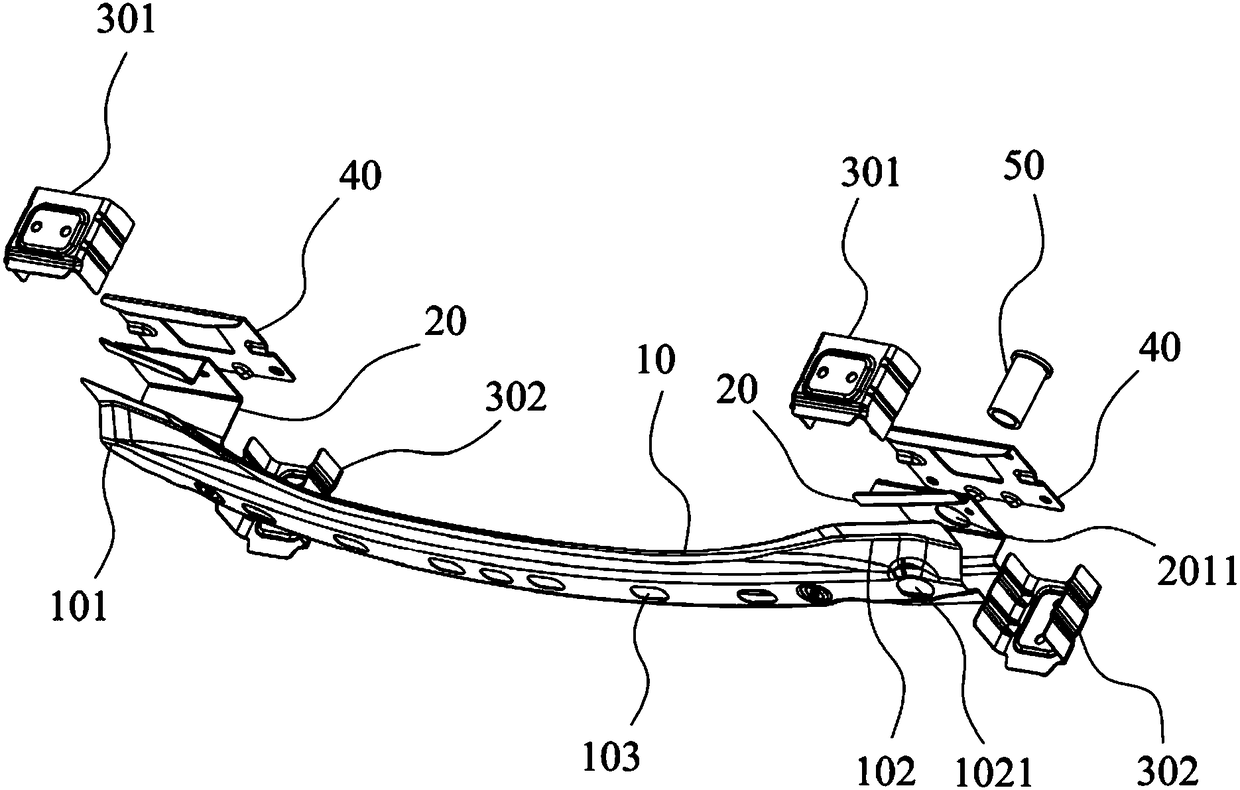
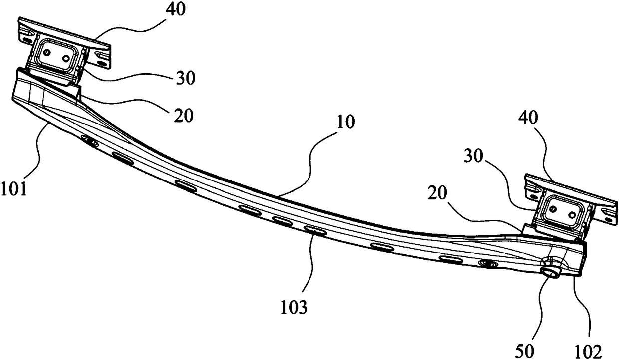
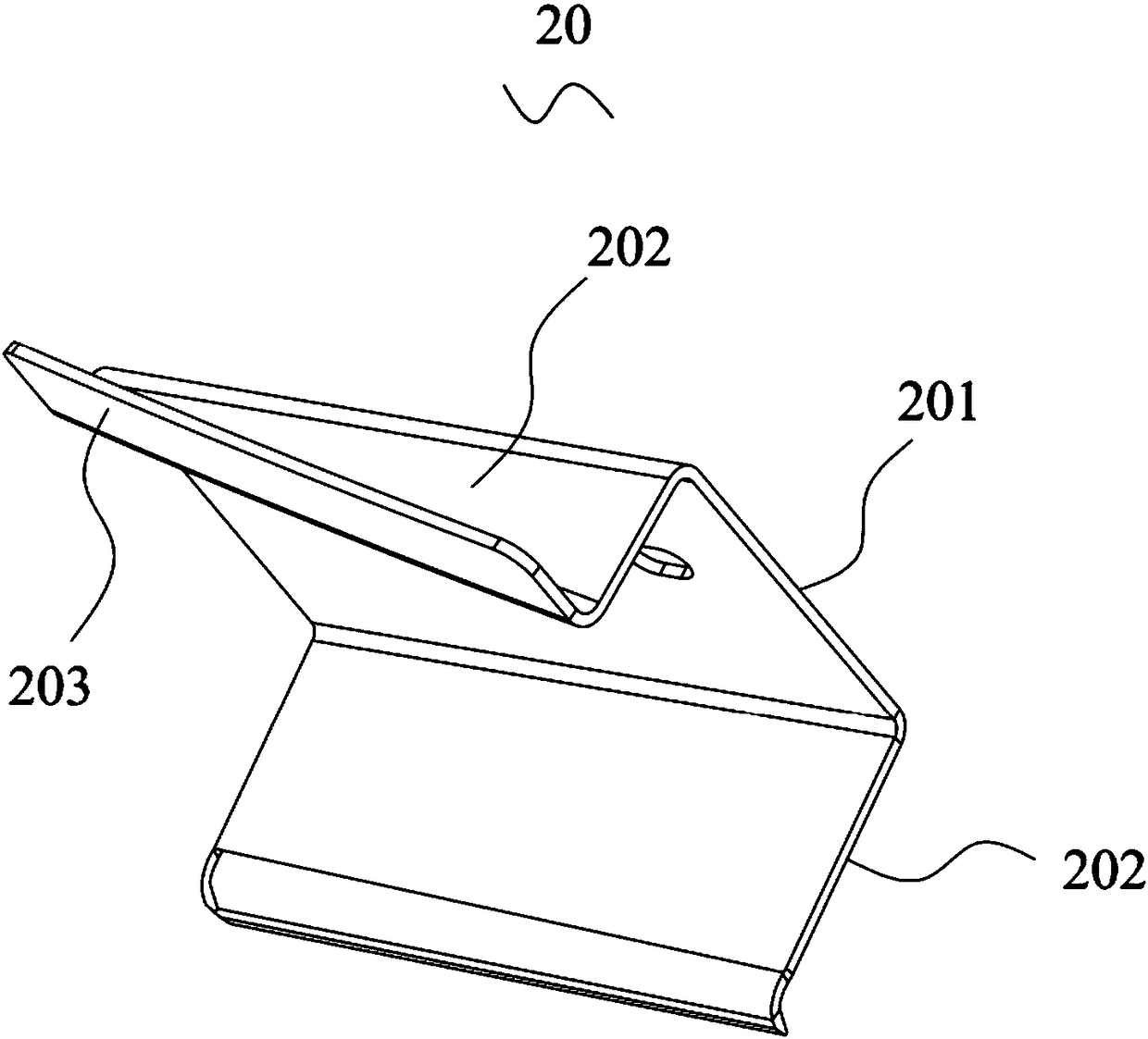
The invention discloses an automobile rear anti-collision beam assembly and further discloses an automobile adopting the automobile rear anti-collision beam assembly. The automobile rear anti-collision beam assembly comprises a rear anti-collision beam outer plate which is in a long-strip shape with the two ends being open. The section of the rear anti-collision beam outer plate is in a U shape, and the rear anti-collision beam outer plate is provided with the first end and the second end which are oppositely arranged and each provided with a rear anti-collision beam inner plate, a rear anti-collision beam energy absorption box and a rear anti-collision beam mounting plate. The rear anti-collision beam inner plates are mounted in a U-shaped cavity of the rear anti-collision beam outer plate and mounted between the rear anti-collision beam outer plate and the rear anti-collision beam energy absorption boxes. The rear anti-collision beam energy absorption boxes are mounted between the rear anti-collision beam mounting plates and the rear anti-collision beam inner plates. The second ends are each provided with a tow hook threaded pipe, and the tow hook threaded pipes are connected with the rear anti-collision beam outer plate and the rear anti-collision beam inner plates located at the second end correspondingly. The problems that the structure is complex, the anti-collision effect is common, and the using function is simplex can be solved.

Description

Technical field [0001] The present invention relates to the technical field of auto parts, in particular to an automobile rear anti-collision beam assembly and an automobile. Background technique [0002] With the rapid development of the automobile industry, automobiles have become one of the indispensable means of transportation for people. In the actual driving process, the speed of the car is usually faster, and the problem of car collision is becoming more and more serious. The car travels at a fast speed, and it may collide with the rear of the car, which will cause a certain threat to the user’s personal safety during the collision. Because the body has a great mass, this impact force is also great. And it is a rigid collision, which will cause certain damage to the rear structure, fuel system and other rear parts of the passenger car, which will affect the long-term use of the passenger car and people's safety. [0003] The rear anti-collision beam assembly of the automob...

Claims


Application Information

Patent Timeline
Patent Type & Authority Applications(China)
IPC IPC(8): B60R19/34B60R19/48B60D1/56
CPCB60R19/34B60D1/56B60R19/48
Inventor 周安华
Owner JIANGLING HLDG
Learn More