DC-DC converter filtering method, device and terminal

A technology of DC-DC and filter devices, which is applied in the direction of output power conversion devices, DC power input conversion to DC power output, instruments, etc., which can solve problems such as the inability to completely eliminate DC-DC converter interference, and improve user experience degree, improve the anti-interference ability, and eliminate the effect of interference

Inactive Publication Date: 2018-07-31
ZTE CORP
View PDF11 Cites 3 Cited by
  • Summary
  • Abstract
  • Description
  • Claims
  • Application Information

AI Technical Summary

Problems solved by technology

[0004] However, the peak voltage generation of the switching node of the DC-DC converter (SW or LW pin of the power chip) is the main source of interference in the DC-DC converter circuit. These interference elimination filtering measures currently used are aimed at the Interference objects and filtering methods used on the interference path cannot completely eliminate the interference of the DC-DC converter

Method used


Image

  • DC-DC converter filtering method, device and terminal
  • DC-DC converter filtering method, device and terminal
  • DC-DC converter filtering method, device and terminal

Examples


Embodiment Construction

[0026] The following will clearly and completely describe the technical solutions in the embodiments of the present invention with reference to the drawings in the embodiments of the present invention.

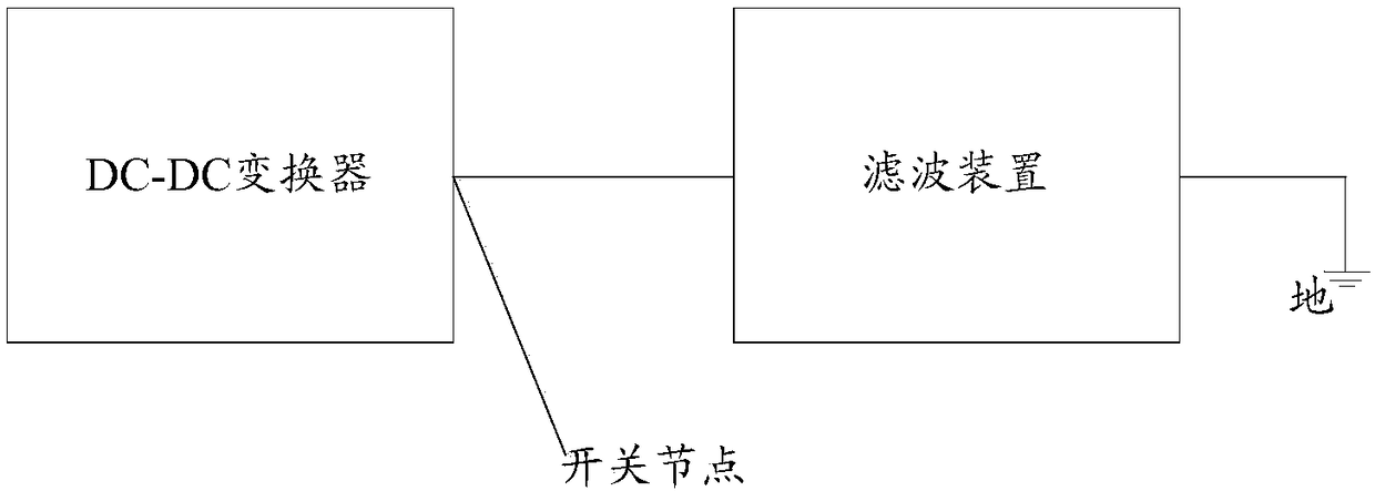
[0027] An embodiment of the present invention provides a filter device for a DC-DC converter, figure 1 It is a structural schematic diagram of the filter device of the DC-DC converter in the embodiment of the present invention, as figure 1 As shown, one end of the filtering device is connected to the switching node of the DC-DC converter, and the other end of the filtering device is grounded;

[0028] Wherein, the filter device is used to eliminate the peak voltage generated at the switch node of the DC-DC converter.

[0029] Here, it should be noted that the peak voltage generated at the switching node of the DC-DC converter is the interference source of the DC-DC converter, then, eliminating the peak voltage generated at the switching node of the DC-DC converter can complet...


PUM


Abstract

The embodiment of the invention discloses a DC-DC converter filtering device. One end of the filtering device is connected to a switching node of the DC-DC converter, and the other end of the filtering device is grounded. The filtering device is used for eliminating a peak voltage generated on the switching node of the DC-DC converter. The embodiment of the invention also discloses a terminal anda DC-DC converter filtering method at the same time.

Description

technical field [0001] The present invention relates to the field of DC-DC converters, in particular to a filtering method, device and terminal for DC-DC converters. Background technique [0002] Switching power supply (also known as DC-DC converter) is more and more widely used in smartphone applications due to its high efficiency, reliable operation, low voltage and high current (such as step-down conversion buck circuit), high voltage (switching DC boost circuit), etc. , such as the core voltage of the CPU, battery charging circuit, backlight circuit and flash drive circuit, etc., but due to the high operating frequency of the switching power supply, a high current change rate (di / dt) and voltage change rate (dv / dt) will be generated inside the circuit ) causes the switching power supply to generate strong electromagnetic interference, and interferes with the radio frequency circuit through coupling channels such as conduction, radiation, and crosstalk. [0003] At prese...

Claims


Application Information

Patent Timeline
Patent Type & Authority Applications(China)
IPC IPC(8): H02M1/14H02M3/155
CPCH02M1/14H02M3/155H02M1/34H02M1/44H02M1/348H02M1/0061H02M3/158
Inventor 蒋发标
Owner ZTE CORP
Why Eureka
Try Eureka