Spatial fast expansion batched test-piece thermal shock test device

An experimental device and thermal shock technology, applied in the direction of measuring devices, instruments, scientific instruments, etc., can solve the problems of low efficiency, low test efficiency, low precision of characterization results, etc., achieve high efficiency and avoid mechanical movement

Inactive Publication Date: 2018-07-31
CHONGQING UNIV
View PDF5 Cites 0 Cited by
  • Summary
  • Abstract
  • Description
  • Claims
  • Application Information

AI Technical Summary

Problems solved by technology

[0005] 1. The surface of the test piece is heated unevenly
During the heating process, the temperature distribution on the surface of the test piece is not uniform, so it is difficult to directly determine the surface temperature of the test piece;
[0006] 2. The target temperature of thermal shock is difficult to control;
[0007] 3. The achievable thermal shock environment is very limited
[0009] 1. It takes a lot of time to install the test piece on the clamping mechanism and guide wire, and only one test piece can be clamped in one experiment, so the efficiency is relatively low
[0010] 2. When the test piece enters the heating furnace, it falls directly onto the buffer pad in the way of free fall, which cannot effectively avoid large mechanical shocks.
[0011] 3. The test piece is in the environment medium, and it is impossible to control the switch of the test piece in various postures, so as to obtain the influence of different postures on the thermal shock of ceramic materials
[0012] 4. Only one experiment can be done at a time, and the environmental impact cannot be eliminated, and the brittle materials are highly dispersed, which makes the accuracy of the characterization results low
[0013] The above problems lead to low test efficiency and errors in experimental data during the test, so that it is difficult to reasonably characterize the thermal shock resistance of ceramic material specimens

Method used


Image

  • Spatial fast expansion batched test-piece thermal shock test device
  • Spatial fast expansion batched test-piece thermal shock test device

Examples


Embodiment Construction

[0024] Below in conjunction with accompanying drawing and embodiment the present invention will be further described:

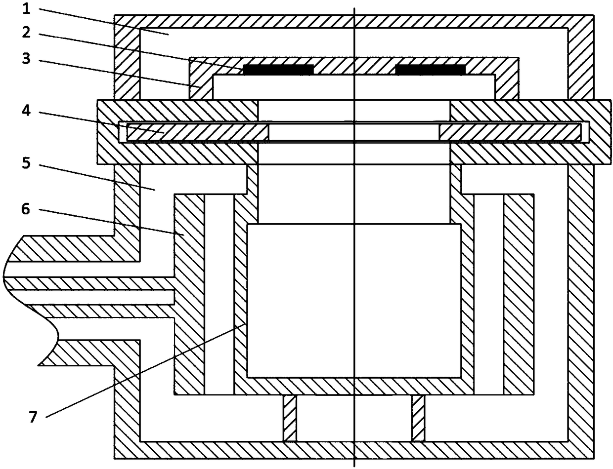
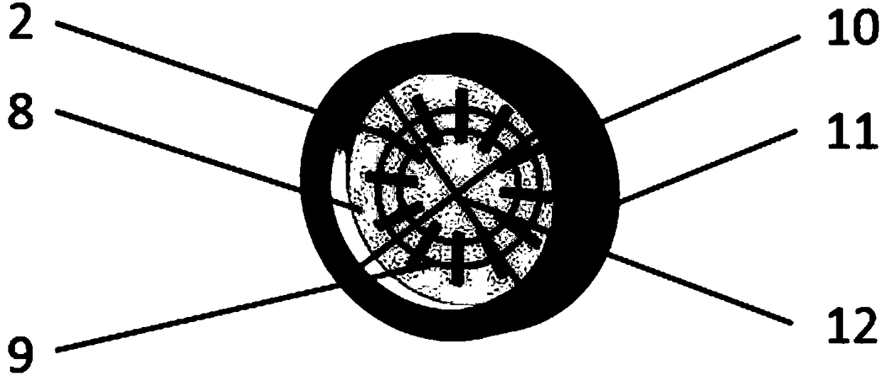
[0025] Such as figure 1 and figure 2 As shown, the present invention includes a test piece placement cavity 1. There is a test piece holder 3 in the test piece placement chamber 1. The outer edge of the test piece holder 3 is a high-strength graphite support 11, the inner layer is a heat-insulating carbon felt 10, and the bottom surface is graphite. Paper 8, insert the batch test pieces 2 into the test piece holder 3, and place the molybdenum wire mesh formed by the crossed molybdenum wire 12 and the molybdenum wire ring 9 at the port of the test piece holder 3 to prevent the test pieces from falling off. A sealed and heat-insulated hatch 4 is installed under the specimen holder 3, and an environmental state control chamber 5 is installed under the sealed and heat-insulated hatch 4. There is a heating furnace 6 in the environmental state control chamber 5, ...


PUM


Abstract

The invention discloses a spatial fast expansion batched test-piece thermal shock test device. The device comprises a test-piece placement cavity (1) and an environmental state control cavity (5); a test-piece holder (3) is installed in the test-piece placement cavity (1) and is composed of a high-strength graphite support (11), thermal insulation carbon felt (10), graphite paper (8) and batched test-pieces (2); the test-piece holder (3) is placed on a sealing thermal insulation bin door (4) between the two cavities; the environmental state control cavity (5) is internally provided with a gasstorage cavity (7) and a heating furnace (6). The device has the advantages that by making the test-pieces static, different thermal environments are realized through the environmental state control cavity, then, the sealing thermal insulation bin door is opened to realize thermal shock of diversified complex thermal environments through fast expansion of the environmental module space, and mechanical movement of the test-pieces is avoided; meanwhile, surface heating of the test-pieces is uniform in the thermal shock process; besides, thermal shock can be performed on multiple test-pieces at atime to conduct the batch test, and the efficiency is high.

Description

technical field [0001] The invention relates to the field of thermal shock resistance tests, in particular to a thermal shock test device for rapid expansion of space and batches of test pieces. Background technique [0002] In recent years, my country's aerospace industry has continuously made major breakthroughs, and national defense and military forces have gradually become stronger. These are inseparable from the rapid development of high-temperature material research and development and characterization methods. The ultra-high temperature materials used in the thermal protection system of hypersonic vehicles such as manned spaceflight, deep space exploration vehicles, missiles and rockets, as well as the hot end parts of engines, often face complex and diverse thermal environments during their service. Taking ultra-high-temperature ceramics as thermal protection materials for hypersonic aircraft as an example, they face different airspaces, different oxygen atmospheres,...

Claims


Application Information

Patent Timeline
Patent Type & Authority Applications(China)
IPC IPC(8): G01N3/60
CPCG01N3/60G01N2203/0226
Inventor 李卫国董攀麻建坐徐念东李莹寇海波邵家兴邓勇陶勇张欣张续耀张先贺方岱宁
Owner CHONGQING UNIV
Why Eureka
Try Eureka