
An air crush structure

An air-type, sliding mechanism technology, applied in steering mechanisms, vehicle components, steering columns, etc., can solve problems such as no damping, little space for improving collision performance, and falling parts.

Active Publication Date: 2020-07-07
ZHEJIANG LEAPMOTOR TECH CO LTD
View PDF10 Cites 0 Cited by
  • Summary
  • Abstract
  • Description
  • Claims
  • Application Information

AI Technical Summary

Problems solved by technology

[0004] 1. The traditional crushing structure has problems such as jamming and falling of parts during the sliding process. The upper shaft and the lower shaft are connected by splines, the sliding process of the splines is not smooth enough, the force value of the energy-absorbing band is unstable, and the collapsed structure is composed of parts Many inconvenience factors,
[0005] 2. The traditional crushing structure has problems such as pipe friction and shear block shearing, which are not easy to control. The friction of the mechanical structure will be affected by processing accuracy and installation technology, resulting in difficult control and high cost.
[0006] 3. The traditional crushing structure has problems such as no sense of damping and little room for improvement in crash performance

Method used


Image

  • An air crush structure
  • An air crush structure
  • An air crush structure

Examples


Embodiment Construction

[0020] The preferred embodiments of the present invention will be described in further detail in conjunction with the accompanying drawings.

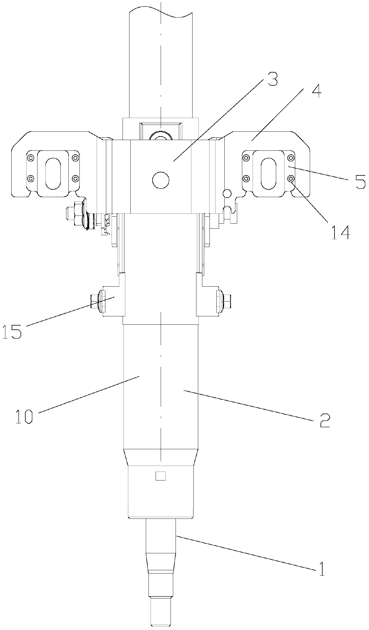
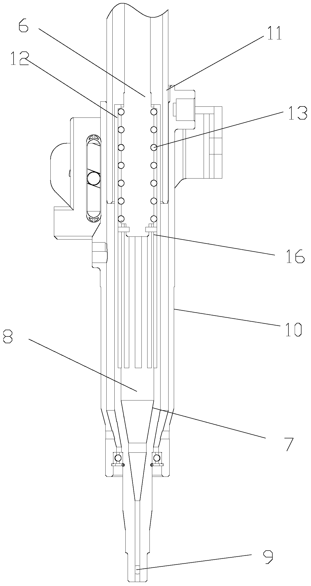
[0021] Such as Figure 1-3 The novel air crushing structure includes a steering column and an outer bushing 2 of the steering column, the outer bushing 2 of the steering column is connected with a connecting bracket 3, and mounting seats are provided on both sides of the connecting bracket 3 4. The mounting base 4 is connected with a shear block 5, and the mounting base 4 is provided with a connection hole 14, and the connection hole 14 is connected with the shear block 5 after injection molding.

[0022] The steering column includes a lower shaft 6 and an upper shaft 7. A closed flexible airtight container 8 is formed inside the upper shaft 7. Compressed air is added into the flexible airtight container 8. The top of the flexible airtight container 8 of the upper shaft 7 An adjustable pressure relief valve 9 is provided, and both side...


PUM


Abstract

The invention discloses a novel air-type crushing structure. According to the technical scheme, the novel air-type crushing structure comprises a steering tube column and a steering tube column outershaft sleeve, the steering tube column outer shaft sleeve is connected with a connecting bracket, and mounting seats are arranged on both sides of the connecting bracket; the mounting seats are connected with shearing blocks, the steering tube column comprises a lower shaft and an upper shaft, a closed flexible sealing container is formed inside the upper shaft, and compressed air is added into the flexible sealing container; the top of the flexible sealing container of the upper shaft is provided with an adjustable pressure relief valve, the two sides of the interior of the a lower tube are provided with embedded grooves correspondingly, and sliding mechanisms are arranged on the embedded grooves; and the two sides of the upper shaft are located between the sliding mechanisms, and one endof the upper shaft is connected with a piston. The crushing force is controlled through the air compression rate or the inflating amount of the flexible sealing container, so that modification of themechanical structure is avoided, and the adjustable pressure relief valve is adjusted to ensure the fact that the collapse force is within a designed range, so that air reverse impact is avoided, andvarious crumple requirements distributed by different finished vehicles are met.

Description

technical field [0001] The invention relates to the technical field of automobiles, in particular to a novel air-type crushing structure. Background technique [0002] The traditional crushing structure is composed of shear blocks, spline shafts, steering column and steering column outer shaft sleeve and other components. When the upper end of the steering column is impacted by a collision, the force on the shear block is greater than its breaking force, the shear block breaks, and the small assembly of the steering column collapses downward. At this time, the spline shaft moves relatively, and the small assembly of the steering column Relative movement occurs with the lower column tube. [0003] The column crushing process is as follows: when the vehicle collides head-on, the vehicle body is first damaged, and the steering column is pushed out, causing the driver to be injured by the impact. When the impact force is greater than the column collapse force, the steering sys...

Claims


Application Information

Patent Timeline
Patent Type & Authority Patents(China)
IPC IPC(8): B62D1/19
CPCB62D1/192
Inventor 赵敏吴齐马涛锋
Owner ZHEJIANG LEAPMOTOR TECH CO LTD
Learn More