Mechanical part surface cleaning equipment
A surface cleaning and mechanical parts technology, applied in the field of mechanical parts surface cleaning equipment, can solve the problems of low cleaning efficiency and insufficient cleaning, and achieve the effect of improving cleaning efficiency
- Summary
- Abstract
- Description
- Claims
- Application Information
AI Technical Summary
Problems solved by technology
Method used
Image

Examples
Embodiment 1
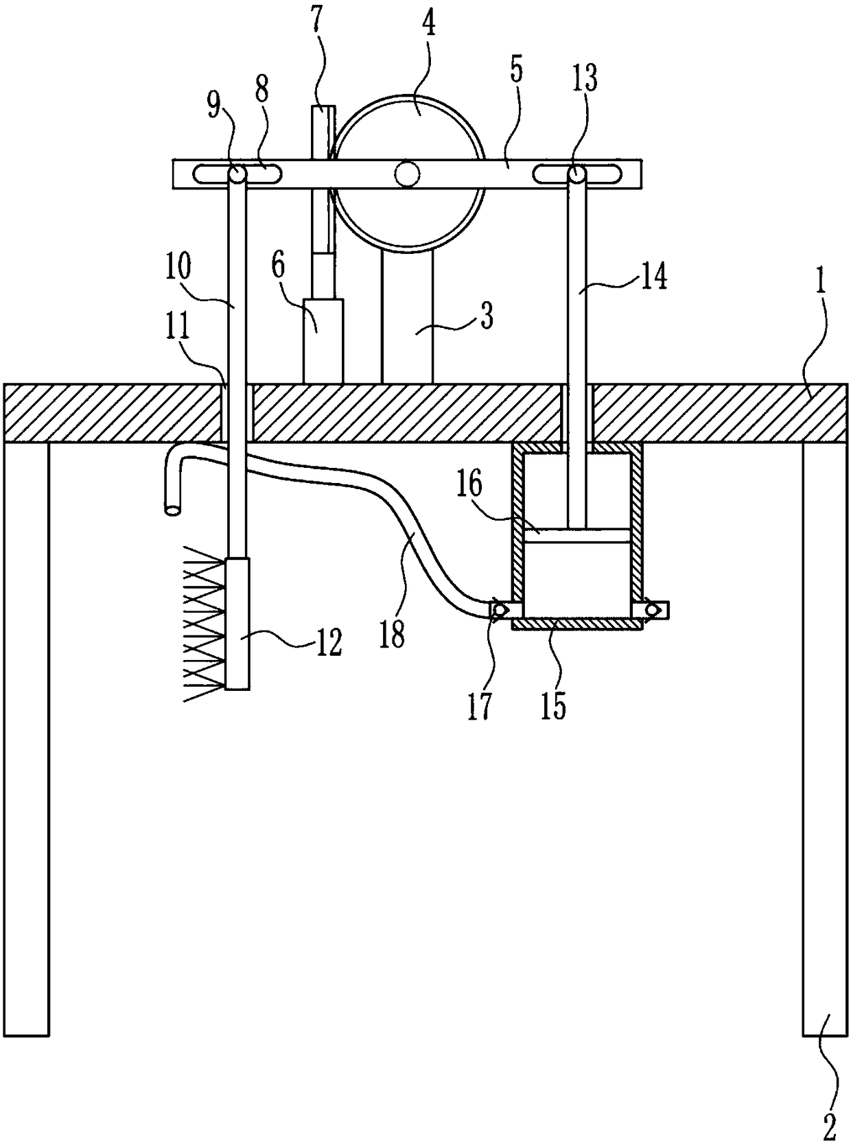
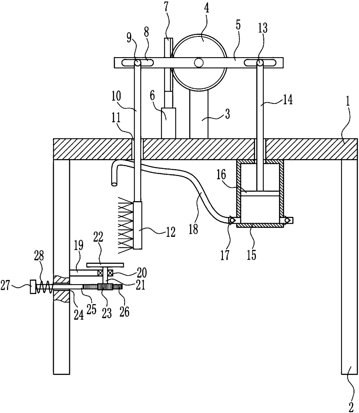
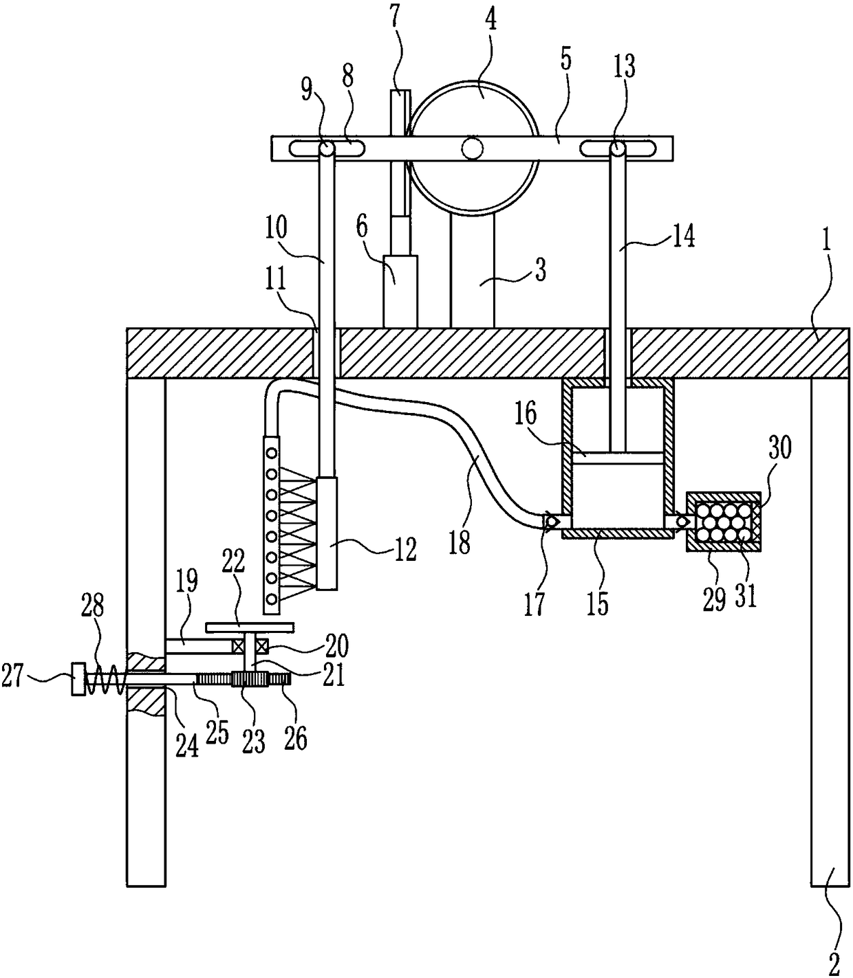
[0022] A device for cleaning the surface of mechanical parts, such as Figure 1-4 As shown, it includes a horizontal plate 1, a support plate 2, a mounting rod 3, a large gear 4, a swing rod 5, a cylinder 6, a first rack 7, a first roller 9, a movable rod 10, a brush 12, a second Roller 13, push rod 14, cylinder body 15, piston 16, one-way valve 17 and air pipe 18, support plates 2 are connected to the left and right sides of the bottom of horizontal plate 1, and installation rod 3 is connected to the middle of the top of horizontal plate 1, The upper front side of the installation rod 3 is rotatably equipped with a large gear 4, the front middle part of the large gear 4 is connected with a swing rod 5, and the middle of the top of the horizontal plate 1 is equipped with a cylinder 6, which is located on the left side of the installation rod 3. The top of 6 is connected with the first rack 7, the first rack 7 is located on the left side of the large gear 4 and behind the swing...
Embodiment 2
[0024] A device for cleaning the surface of mechanical parts, such as Figure 1-4As shown, it includes a horizontal plate 1, a support plate 2, a mounting rod 3, a large gear 4, a swing rod 5, a cylinder 6, a first rack 7, a first roller 9, a movable rod 10, a brush 12, a second Roller 13, push rod 14, cylinder body 15, piston 16, one-way valve 17 and air pipe 18, support plates 2 are connected to the left and right sides of the bottom of horizontal plate 1, and installation rod 3 is connected to the middle of the top of horizontal plate 1, The upper front side of the installation rod 3 is rotatably equipped with a large gear 4, the front middle part of the large gear 4 is connected with a swing rod 5, and the middle of the top of the horizontal plate 1 is equipped with a cylinder 6, which is located on the left side of the installation rod 3. The top of 6 is connected with the first rack 7, the first rack 7 is located on the left side of the large gear 4 and behind the swing ...
Embodiment 3
[0027] A device for cleaning the surface of mechanical parts, such as Figure 1-4 As shown, it includes a horizontal plate 1, a support plate 2, a mounting rod 3, a large gear 4, a swing rod 5, a cylinder 6, a first rack 7, a first roller 9, a movable rod 10, a brush 12, a second Roller 13, push rod 14, cylinder body 15, piston 16, one-way valve 17 and air pipe 18, support plates 2 are connected to the left and right sides of the bottom of horizontal plate 1, and installation rod 3 is connected to the middle of the top of horizontal plate 1, The upper front side of the installation rod 3 is rotatably equipped with a large gear 4, the front middle part of the large gear 4 is connected with a swing rod 5, and the middle of the top of the horizontal plate 1 is equipped with a cylinder 6, which is located on the left side of the installation rod 3. The top of 6 is connected with the first rack 7, the first rack 7 is located on the left side of the large gear 4 and behind the swing...
PUM
 Abstract
Description
Claims
Application Information
 - R&D
- Intellectual Property
- Life Sciences
- Materials
- Tech Scout
- Unparalleled Data Quality
- Higher Quality Content
- 60% Fewer Hallucinations
Browse by: Latest US Patents, China's latest patents, Technical Efficacy Thesaurus, Application Domain, Technology Topic, Popular Technical Reports.
© 2025 PatSnap. All rights reserved.Legal|Privacy policy|Modern Slavery Act Transparency Statement|Sitemap|About US| Contact US: help@patsnap.com