Load state detection method, device and circuit, air conditioner controller

A load state detection and working state technology, applied in the fields of air conditioner controllers, load state detection methods, devices and circuits, can solve the problems of inability to accurately locate faults, complex components of air conditioner controllers, waste of manpower and material resources, etc. The effect of quickly and accurately locating faults, improving after-sales service quality, and reducing manpower and material resources

Active Publication Date: 2019-10-22
GREE ELECTRIC APPLIANCES INC
View PDF7 Cites 0 Cited by
  • Summary
  • Abstract
  • Description
  • Claims
  • Application Information

AI Technical Summary

Problems solved by technology

[0003] However, in the actual use of the air conditioner, due to the influence of various factors such as man-made or working environment, the air conditioner controller often has various and complicated faults when it is working, and the entire air conditioner product will be paralyzed at this time
[0004] Due to the complex composition of air-conditioning controller components, it is impossible to accurately locate the fault under normal circumstances. At this time, it is necessary to rebuild the experimental environment to review the fault information after returning the faulty product after sales. In this process, a lot of manpower will be wasted. and physical resources

Method used


Image

  • Load state detection method, device and circuit, air conditioner controller
  • Load state detection method, device and circuit, air conditioner controller
  • Load state detection method, device and circuit, air conditioner controller

Examples


Embodiment 1

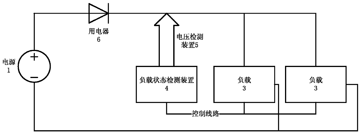
[0126] Figure 5 It is a schematic diagram of some other embodiments of the load state detection method of the present invention. Figure 5 The embodiment adopts such as figure 2 The load status detection circuit shown. Among them, the electric appliance 6 adopts a diode, and the diode is placed on the general circuit of the circuit, and the voltage detection module 5 respectively detects the voltage at both ends of the diode; and the actuator (load 3) is placed in the circuit.

[0127] Such as Figure 5 As shown, the load state detection method may include:

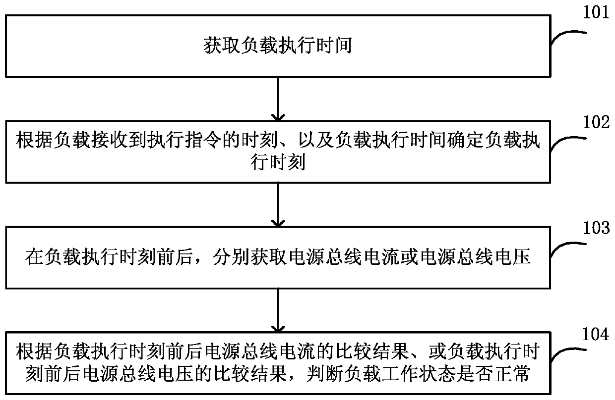
[0128] In step 501, the load state detecting device 4 sends an operation instruction to the load 3 (air conditioner controller device).

[0129] Step 502, after the actuator (load) receives the execution command from the controller, it will take a period of delay T1 before it can act. In the initial working state of the device, its voltage jitter range is large, and the detection is performed immediately at this ti...

Embodiment 2

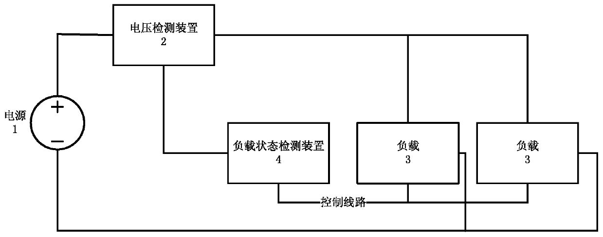
[0138] In the case that the air conditioner controller includes multiple actuators, since it needs to judge a single actuator, the control method is somewhat different from the traditional control method. Interval control needs to be implemented, that is, only one actuator is executed each time, and the load execution time T1 and load execution time t1 are calculated for the execution time of each actuator, and the predetermined time period T2 before the load execution time t1 and after the load execution time t1 During the predetermined time period T2, the detection circuit judges the bus, and since only one actuator is executed, it can be determined that the actuator is the action when a change is detected. After the predetermined time period T2 after the load execution time t1, the next actuator will perform detection again.

[0139] It can thus be determined that the time T required by the load state detection device to detect an actuator is the sum of the load execution t...


PUM


Abstract

A load state detection method, device and circuit, and an air conditioner controller. The method comprises: acquiring a load execution time (101); determining a load execution moment according to a moment when a load receives an execution instruction and the load execution time (102); respectively acquiring a power supply bus current or a power supply bus voltage both before and after the load execution moment (103); and according to a comparison result of the power supply bus current before and after the load execution moment or a comparison result of the power supply bus voltage before and after the load execution moment, determining whether the working state of the load is normal (104). When a fault occurs in an air conditioner controller device, the fault can be quickly and accurately located.

Description

technical field [0001] The invention relates to the field of air conditioner controllers, in particular to a load state detection method, device and circuit, and an air conditioner controller. Background technique [0002] As the brain of the air conditioner, the air conditioner controller plays an indispensable role in the entire life cycle of the air conditioner product. [0003] However, in the actual use of the air conditioner, due to the influence of various factors such as man-made or working environment, the air conditioner controller often has various and complicated faults when it is working, and the entire air conditioner product will be paralyzed at this time. [0004] Due to the complex composition of air-conditioning controller components, it is impossible to accurately locate the fault under normal circumstances. At this time, it is necessary to rebuild the experimental environment to review the fault information after returning the faulty product after sales. ...

Claims


Application Information

Patent Timeline
Patent Type & Authority Patents(China)
IPC IPC(8): F24F11/38
CPCF24F11/38F24F11/62F24F2140/50
Inventor 陈万兴郭双林钱沛周葆林庞维容刘红燕吴宝龙
Owner GREE ELECTRIC APPLIANCES INC
Why Eureka
Try Eureka