Flush toilet bowl device

A toilet and flushing technology, which is applied in water supply devices, sanitary equipment for toilets, buildings, etc., can solve problems such as blockage of flow paths and narrowing of flow paths of centrifugal pumps

Active Publication Date: 2018-07-27
TOTO LTD
View PDF7 Cites 0 Cited by
  • Summary
  • Abstract
  • Description
  • Claims
  • Application Information

AI Technical Summary

Problems solved by technology

However, in order to generate high pressure, the flow path of this centrifugal pump needs to be narrowed, so there is a problem that the flow path will be blocked if a large amount of dirt or the like flows in.

Method used


Image

  • Flush toilet bowl device
  • Flush toilet bowl device
  • Flush toilet bowl device

Examples


Embodiment Construction

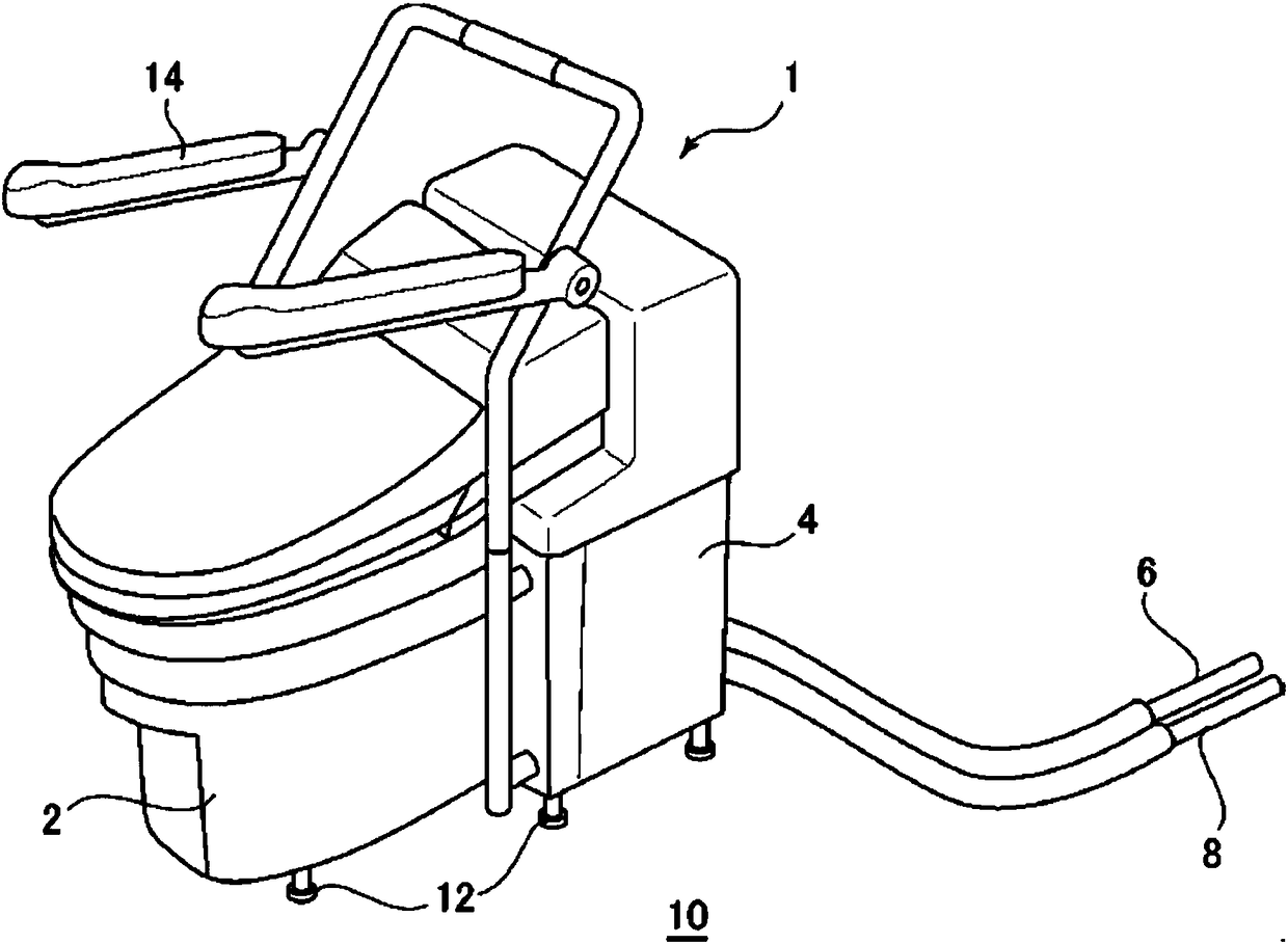
[0031] Next, a flush toilet device according to an embodiment of the present invention will be described with reference to the drawings. start through figure 1 and figure 2 The overall structure of the flush toilet device according to the embodiment of the present invention will be described. figure 1 is an overall perspective view showing the flush toilet device according to the embodiment of the present invention, figure 2 It is an overall configuration diagram showing the flush toilet device according to the embodiment of the present invention.

[0032] Such as figure 1 As shown, the flush toilet device 1 according to the present embodiment is a non-fixed flush toilet device that can be used as a nursing care flush toilet device that is placed next to a bed. The flush toilet device 1 is provided with: a toilet body 2; a pulverizing pressure conveying device 4 for pulverizing and conveying the dirt and cleaning water discharged from the toilet body 2 under pressure;...


PUM


Abstract

To provide a flush toilet bowl device that prevents disabling of rotation of a disk part due to entanglement and accumulation of fibrous foreign matters between the disk part and a pressure feeding part. The flush toilet bowl device of the present invention is of a non-installed type, and includes a crushing part for decomposing sewage by stream current decomposition, and a pressure feeding part 36 for pressure-feeding the crushed sewage and flushing water. The pressure feeding part 36 is the centrifugal-type pressure feeding part 36 having an impeller 62 disposed on an inner side of a side wall of the pressure feeding part, the impeller 62 including a disk part 66 and a protrusion 68, and a radial-direction flow channel 74 and a circumferential-direction flow channel 76. A side wall 64 ofthe pressure feeding part 36 includes a crushing region 78 of the side wall 64 and a regulating part 80, the crushing region being a region where the sewage flowing from the radial-direction flow channel 74 toward the circumferential-direction flow channel 76 crushes with the flushing water due to centrifugal force generated by rotation of the impeller 62, and the regulating part being formed between the crushing region and a gap part 70 formed between the side wall 64 and the disk part 66 and inhibiting the sewage and the flushing water from flowing into the gap part 70 from the crushing region.

Description

[0001] technology area [0002] The invention relates to a flush toilet device, in particular to a non-fixed flush toilet device. Background technique [0003] Patent Document 1 proposes a non-fixed flush toilet device (a pressure-feeding toilet device) used as a nursing care flush device arranged next to a bed in a user's living room. In this flush toilet device, dirt is pulverized by agitation of water flow in a pulverization unit, and the pulverized dirt is pressure-feeded by a pressure-feeding unit and discharged to the outside. [0004] In this conventional flush toilet device, even when foreign matter other than dirt and toilet paper (toilet paper) (foreign matter that cannot be crushed) is mistakenly flushed away, the foreign matter remains in the water storage tank, and there is no Sometimes the driving unit such as the electric motor is locked and cannot be used, so the user can continue to use the toilet device. In a flush toilet device used as a toilet device for ...

Claims


Application Information

Patent Timeline
IPC IPC(8): E03D9/00E03D9/10
CPCE03D9/00E03D9/10
Inventor 吉冨利彦
Owner TOTO LTD
Why Eureka
Try Eureka