
Continuous quenching device for jacking chain wheel workpiece

A technology of quenching device and hoisting chain, applied in the direction of quenching device, manufacturing tool, furnace, etc., can solve the problems of not being suitable for mass production, difficult to overcome batch quality problems, low efficiency of manual moving, etc., to avoid oxidation, ensure The effect of thermal stability

Pending Publication Date: 2018-07-27
ZHEJIANG SHUANGNIAO MACHINERY
View PDF0 Cites 2 Cited by
  • Summary
  • Abstract
  • Description
  • Claims
  • Application Information

AI Technical Summary

Problems solved by technology

Since the workpiece is exposed to the outside air during the handling process, the workpiece has the disadvantage of secondary oxidation, and the manual handling has the disadvantage of low work efficiency, and it belongs to intermittent rather than continuous operation, which is not suitable for mass production, and it is difficult to overcome the batch quality problem. In view of this, it is necessary to improve the quenching device for the existing lifting sprocket workpiece

Method used


Image

  • Continuous quenching device for jacking chain wheel workpiece
  • Continuous quenching device for jacking chain wheel workpiece
  • Continuous quenching device for jacking chain wheel workpiece

Examples


Embodiment Construction

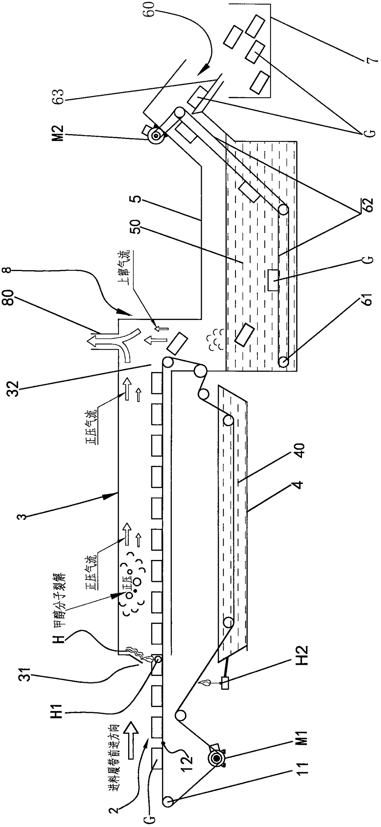
[0014] See figure 1 As shown, the continuous quenching device for the workpiece of the lifting sprocket includes a feeding motor M1, a feeding crawler 12, a feeding roller 11, a feeding area 2, a heating furnace area 3, a cooling tank 4, and a quenching medium The quenching tank 5 of 50, the discharge lifting part and the receiving frame 7, the feeding area 2 is located directly in front of the heating furnace area 3, and corresponds to the inlet side 31 of the heating furnace area 3, and the feeding motor M1 is located in the feeding area 2 Below, the quenching tank 5 is adjacent to the outlet side 32 of the heating furnace area 3, and the feeding motor M1 drives the feeding crawler 12 to advance continuously through the driving feed transmission part, so that the feeding crawler 12 circulates through the feeding area 2 and the heating furnace area 3. The cooling tank 4, the feed roller 11 rotates with the feed crawler 12; the discharge lifting part is arranged in the quenchi...


PUM


Abstract

The invention discloses a continuous quenching device for jacking a chain wheel workpiece. The continuous quenching device for jacking the chain wheel workpiece comprises a feeding motor, a feeding caterpillar band, a feeding roller, a feeding area, a heating furnace area, a cooling groove, a quenching groove and a discharging hoisting part arranged in the quenching groove; the quenching groove isadjacent to the outlet side of the heating furnace area; the feeding motor drives a feeding transmission part to drive the feeding caterpillar band to continuously march to cyclically pass through the feeding area, the heating furnace area and the cooling groove; a discharging motor drives a discharging roller to drive a discharging caterpillar band to continuously march to conveying the workpiece to be discharged; the inlet side of the heating furnace area is provided with a methanol first spraying port, and after ignition, a fire curtain scouring the whole inlet side can be formed; and theside, where the feeding caterpillar band moves out of the cooling groove, on the cooling groove is provided with a methanol second spraying port, and after ignition, it is used for drying the feedingcaterpillar band under high temperature. After the scheme is adopted, production is efficient, the formed fire curtain prevents oxygen-containing air from entering the heating furnace area, it is avoided that oxygen-containing water vapor enters the heating furnace area along with the feeding caterpillar band, and therefore oxidization of the workpiece in a furnace is effectively avoided.

Description

【Technical field】 [0001] The invention relates to a continuous quenching device for lifting sprocket workpieces, belonging to the technical field of heat treatment of lifting sprocket workpieces. 【Background technique】 [0002] The existing quenching device for lifting sprocket workpieces (hereinafter referred to as workpieces) includes heating furnaces and quenching furnaces that are independent of each other. The workpieces are first placed in the heating furnace and filled with reducing gas. In the quenching tank filled with quenching medium to complete the quenching operation. Since the workpiece is exposed to the outside air during the handling process, the workpiece has the disadvantage of secondary oxidation, and the manual handling has the disadvantage of low work efficiency, and it belongs to intermittent rather than continuous operation, which is not suitable for mass production, and it is difficult to overcome the batch quality problem. In view of this, it is rea...

Claims


Application Information

Patent Timeline
IPC IPC(8): C21D9/32C21D1/63C21D1/74
CPCC21D1/63C21D1/74C21D9/0062C21D9/32
Inventor 单伟军楼伟黄文胜叶小江陈良
Owner ZHEJIANG SHUANGNIAO MACHINERY
Learn More