Protective device during communication equipment transportation

A protection device and communication equipment technology, applied in transportation and packaging, packaging, packaging food, etc., can solve problems such as difficult construction, weak scalability, equipment offset, etc., to reduce maintenance risks, improve handling efficiency, and reduce accidents risk effect

Inactive Publication Date: 2018-07-27
江苏仟略信息技术有限公司
View PDF0 Cites 5 Cited by
  • Summary
  • Abstract
  • Description
  • Claims
  • Application Information

AI Technical Summary

Problems solved by technology

[0002] Communication equipment includes wired communication equipment and wireless communication equipment used in industrial control environments. Wired communication means that communication equipment needs to be connected by cables, that is, transmission media such as overhead cables, coaxial cables, optical fibers, and audio cables. In the way of information, the biggest advantage of wired communication equipment is strong anti-interference, high stability, certain confidentiality, fast transmission rate, and infinite bandwidth. However, wired communication is greatly affected by the environment, with weak scalability and attenuation. The construction is difficult, the mobility is poor, and the cost is high
[0003] At present, communication equipment on the market is widely used, and the power is connected through manual handling and installation to facilitate people's lives. However, for the handling of communication equipment, due to the high cost of communication equipment, the equipment may be damaged due to bumps during transportation. damage, resulting in economic losses; and the inertia of the communication equipment itself may cause the equipment to shift during handling, making it difficult for workers to carry

Method used


Image

  • Protective device during communication equipment transportation
  • Protective device during communication equipment transportation
  • Protective device during communication equipment transportation

Examples


Embodiment Construction

[0018] The following will clearly and completely describe the technical solutions in the embodiments of the present invention with reference to the accompanying drawings in the embodiments of the present invention. Obviously, the described embodiments are only some of the embodiments of the present invention, not all of them. Based on the embodiments of the present invention, all other embodiments obtained by persons of ordinary skill in the art without making creative efforts belong to the protection scope of the present invention.

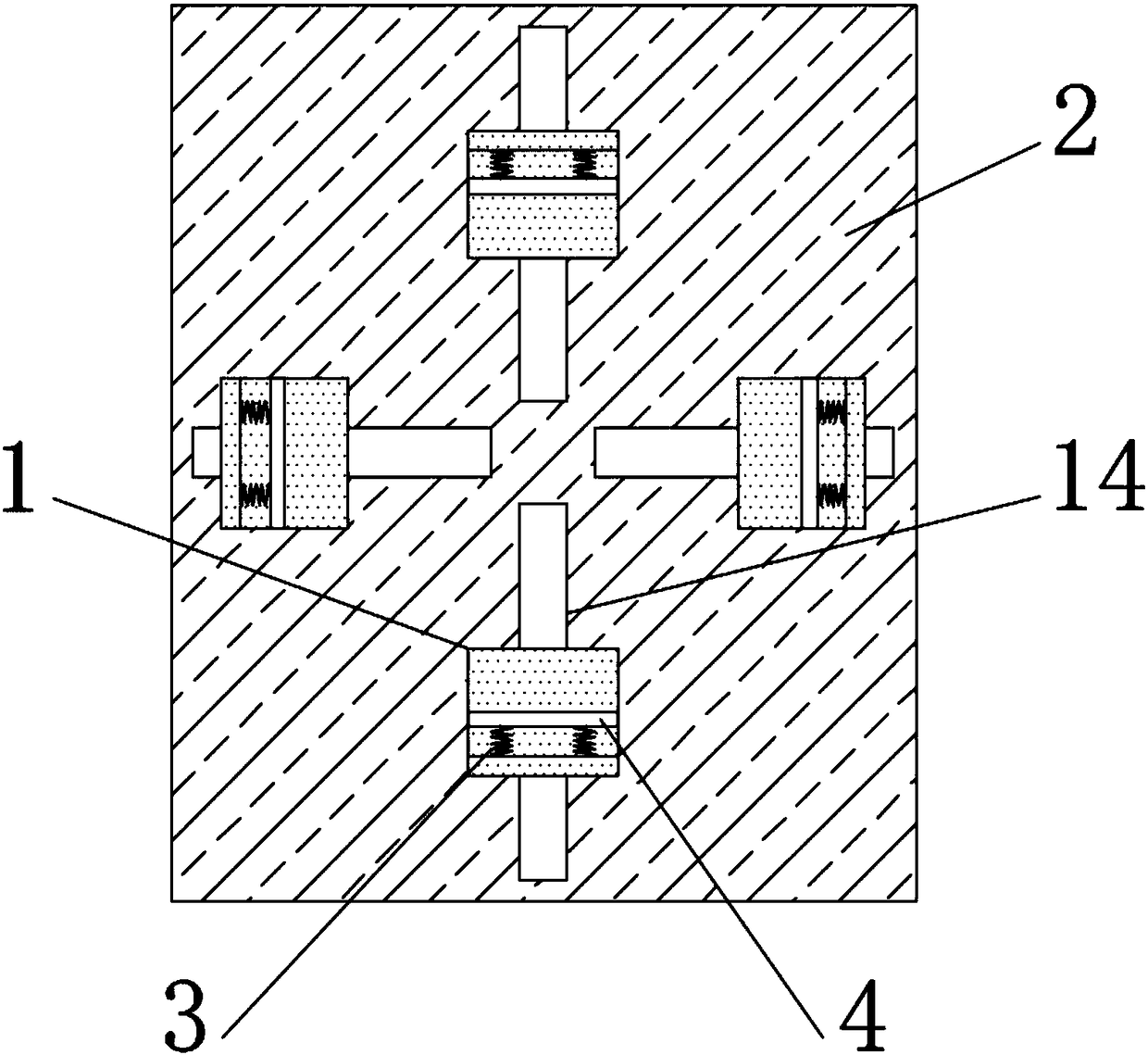
[0019] see Figure 1-3 As shown, a protection device for communication equipment during transportation, including a limiting plate 1 and a base 2 located at the bottom of the limiting plate 1, a first spring 3 is fixedly connected to one side of the limiting plate 1, and the The end of the first spring 3 is fixedly connected with a buffer plate 4, and the movement of the buffer plate 4 prevents the equipment from shifting. The bottom end of the ...


PUM


Abstract

The invention discloses a protective device during communication equipment transportation. The protective device comprises a limiting plate, a base, first springs, buffer plates, fixed columns, sleeves, second springs, third springs, a fixed shaft, a rotary shaft, rollers, a connecting rod, a slide block, a slide slot, a pressure block, a screw, a rotary disc, a fixed block, rotary rods, slide rods and blocking slots. The protective device during communication equipment transportation is simple in structure and is convenient to operate; the rotary disc is rotated, so that a limiting plate is fixed by rotating the rotary disc, and therefore, the device is conveniently stabilized, and shift caused by inertia when the device is transported is avoided; through the action of the buffer plate, collision of the device is avoided, so that economical burden caused by damages on the device is prevented; and the protective device during communication equipment transportation is prevented from being damaged as a result of bumps in the road during transportation as a spring on the top of the rotary shaft and the sleeve co-damp, and therefore, transportation efficiency is reduced, accident riskis reduced, and maintenance risk caused by damages of the device is reduced as much as possible.

Description

technical field [0001] The invention relates to a protection device, in particular to a protection device for communication equipment during transportation, and belongs to the technical field of communication equipment transportation. Background technique [0002] Communication equipment includes wired communication equipment and wireless communication equipment used in industrial control environments. Wired communication means that communication equipment needs to be connected by cables, that is, transmission media such as overhead cables, coaxial cables, optical fibers, and audio cables. In the way of information, the biggest advantage of wired communication equipment is strong anti-interference, high stability, certain confidentiality, fast transmission rate, and unlimited bandwidth. However, wired communication is greatly affected by the environment, with weak scalability and attenuation. The construction is difficult, the mobility is poor, and the cost is high. [0003...

Claims


Application Information

Patent Timeline
IPC IPC(8): B65D25/10B65D81/07B65D81/05B65D85/68
CPCB65D25/101B65D81/05B65D81/07B65D85/68
Inventor 徐以珍胡燕
Owner 江苏仟略信息技术有限公司
Why Eureka
Try Eureka