Tractor frame and traveling wheel system

A tractor and walking wheel technology, applied in the field of tractors, can solve problems such as frame failure, difficulty in overcoming obstacles, intermittent jumping, etc., and achieve improved force bearing effect and vibration reduction effect, good vibration reduction and anti-vibration effects, and good bearing The effect of load capacity

Active Publication Date: 2018-07-27
XINGGUANG AGRI MACHINERY
View PDF10 Cites 0 Cited by
  • Summary
  • Abstract
  • Description
  • Claims
  • Application Information

AI Technical Summary

Problems solved by technology

[0002] Existing crawler tractors have been widely used, but in fact, there are still many deficiencies, for example, in terms of the frame: the front and rear beams are directly connected, the vibration is large, the frame is easy to crack, and the operation is easy to fatigue; the support beam directly Opening holes to connect supporting rollers reduces the load-bearing capacity, insufficient support beam strength, and poor reliability; the structure is complex and the cost is high. The reason is that strong vibrations will occur when the tractor is powered, the tractor is transferred, and the working parts are operated. Vibration causes frame fatigue cracks, strength decline, and frame failure; direct-connected frame vibration causes vibration of the whole machine, operators are prone to fatigue, and even causes operator disease. In order to increase strength, many reinforcing ribs are added, and the structure is complicated. The cost increases, for example, in terms of the road wheel system: when encountering uneven roads during driving, the center of gravity of the whole machine also fluctuates up and down with the road surface, the machine vibrates severely when bumping up and down, the machine is easy to be damaged, and the operation is easy to fatigue; The machine will be jacked up, the attached area of ​​the track belt is small, the traction force is reduced, and the machine is difficult to overcome obstacles; it will jump intermittently when turning; it is easy to drop the track. The reason is that the prior art rollers are fixed or one group is floating. , the center of gravity of the machine fluctuates greatly during operation, and the machine will pass through forcibly when encountering an obstacle, causing great shock and vibration; when encountering a relatively large obstacle, the whole machine will be jacked up, the machine will be suspended in the air, the ground contact area of ​​the track will be reduced, and the traction force will decrease; deep mud feet When turning sharply, the guide iron crosses the track teeth, causing the track to derail and fall out

Method used


Image

  • Tractor frame and traveling wheel system
  • Tractor frame and traveling wheel system
  • Tractor frame and traveling wheel system

Examples


Embodiment 1

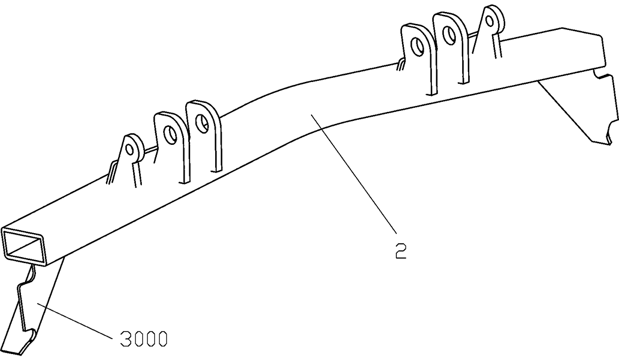
[0039] Example 1, such as figure 1 , 2 , 3, 4, and 5, a tractor frame includes a front support beam 1 and a rear support beam 2 oppositely arranged front and rear, between the left end of the front support beam 1 and the left end of the rear support beam 2 and A side support longitudinal beam 3 is fixed between the right end of the front support beam 1 and the right end of the rear support beam 2, the middle part of the front support beam 1 arches upwards, and the middle part of the rear support beam 2 Arched upwards, the side support longitudinal beam 3 includes a main support beam 31 straightly extending front and rear, and a front slant beam 32 fixed to the front end of the main support beam 31 and extending obliquely forward and downward for installing the tensioning wheel 41 A rear slanting beam 33 extending obliquely to the rear and downward and used for installing the fixed wheel 42 is fixed to the rear end of the main support beam 31 . In this frame, the front suppor...

Embodiment 2

[0049] Example 2, such as Image 6 , 7 , 8, 9, 10, and 11, a tractor road wheel system includes the tractor frame described in Embodiment 1, and also includes two front slanting beams 32 respectively installed on the left and right sides. Said tensioning pulley 41, two fixed wheels 42 installed on the left and right sides of said rear inclined beam 33, two left and right oppositely arranged drive wheels 43, two left and right oppositely arranged caterpillar belts 44, said left and right sides A front roller assembly with a roller 7 is installed on the front suspension assembly, and a rear roller assembly with a roller 7 is installed on the rear suspension assemblies on the left and right sides, and each track 44 The driving wheel 43 wound on the same side, the roller 7 of the front roller assembly, the roller 7 of the rear roller assembly, the fixed wheel 42 and the On the driving wheel 43, the driving wheel 43 on the left and right sides is driven by the same driving device...


PUM


Abstract

The invention relates to the technical field of tractors, in particular to a tractor frame and a traveling wheel system. The tractor frame comprises a front supporting cross beam and a rear supportingcross beam which are disposed opposite to each other. Side supporting longitudinal beams are fixed between the left end of the front supporting cross beam and the left end of the rear supporting cross beam and between the right end of the front supporting cross beam and the right end of the rear supporting cross beam. The intermediate portion of the front supporting cross beam is arched upwards,and the intermediate portion of the rear supporting cross beam is arched upwards. The side supporting longitudinal beams include main supporting beams, front oblique beams and rear oblique beams, wherein the main supporting beams extend forwards and backwards in a linear mode, the front oblique beams extending obliquely forwards and downwards are fixed to the front ends of the main supporting beams and used for mounting tensioning wheels, and the rear oblique beams extending obliquely backwards and downwards are fixed to the rear ends of the main supporting beams and used for mounting fixed wheels. The structure is more stable, an operator is more comfortable to use, and the operation is more cheerful.

Description

technical field [0001] The invention relates to the technical field of tractors, in particular to a tractor frame and a road wheel system. Background technique [0002] Existing crawler tractors have been widely used, but in fact, there are still many deficiencies, for example, in terms of the frame: the front and rear beams are directly connected, the vibration is large, the frame is easy to crack, and the operation is easy to fatigue; the support beam directly Opening holes to connect supporting rollers reduces the load-bearing capacity, insufficient support beam strength, and poor reliability; the structure is complex and the cost is high. The reason is that strong vibrations will occur when the tractor is powered, the tractor is transferred, and the working parts are operated. Vibration causes frame fatigue cracks, strength decline, and frame failure; direct-connected frame vibration causes vibration of the whole machine, operators are prone to fatigue, and even causes o...

Claims


Application Information

Patent Timeline
Patent Type & Authority Applications(China)
IPC IPC(8): B62D21/18B62D55/14B62D55/30B62D55/08
CPCB62D21/18B62D55/08B62D55/14B62D55/30
Inventor 毛智琳柳中泉彭铭广刘文兵周士林朱森荣
Owner XINGGUANG AGRI MACHINERY
Why Eureka
Try Eureka