Electric automobile braking device

A braking device, electric vehicle technology, applied in the direction of braking transmission device, braking action starting device, electric vehicle, etc., can solve the problems of cost increase, consumption, battery charging, etc., and achieve the effect of preventing the braking feeling from declining

Active Publication Date: 2018-07-27
HONDA MOTOR CO LTD
View PDF6 Cites 0 Cited by
  • Summary
  • Abstract
  • Description
  • Claims
  • Application Information

AI Technical Summary

Problems solved by technology

[0002] The place where the battery of the electric vehicle is charged by an external power source is a place with high altitude, and when the battery is fully charged and driven downhill for a long time, since the battery cannot be further charged, regenerative braking of the motor cannot be performed. The potential energy recovered by regenerative braking is wasted in vain, and there is a problem of increasing the cost of charging with an external power source

Method used


Image

  • Electric automobile braking device
  • Electric automobile braking device
  • Electric automobile braking device

Examples


Embodiment Construction

[0040] The following is based on Figure 1 to Figure 8 , to describe the embodiment of the present invention.

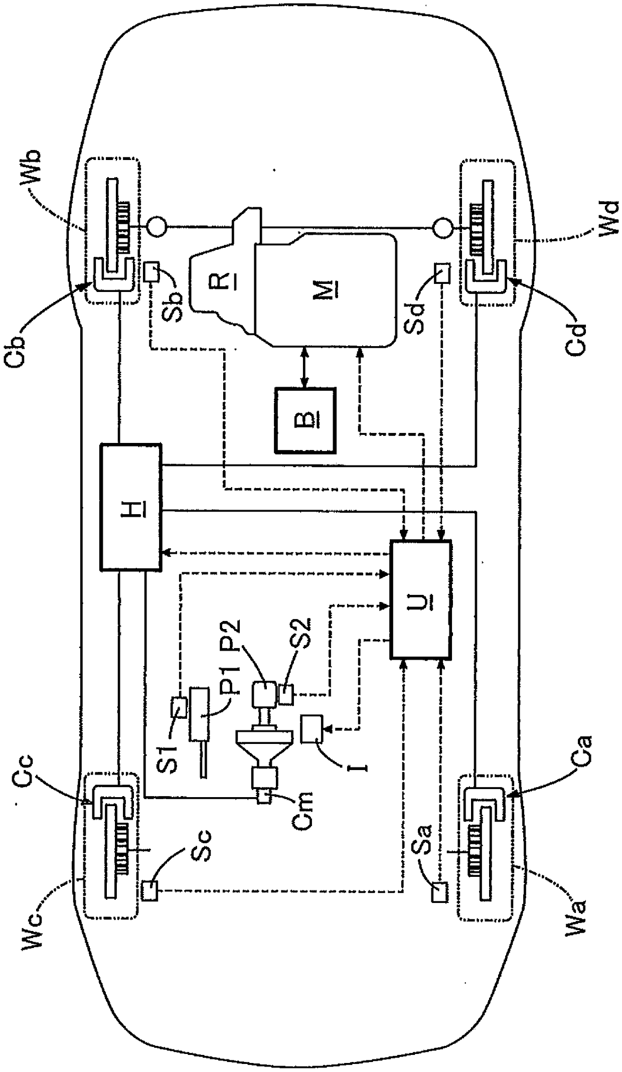
[0041] Such as figure 1 As shown, the vehicle of the present embodiment includes left and right front wheels Wa, Wc as driven wheels, and left and right rear wheels Wd, Wb as drive wheels. M drive. The electric motor M is driven by electric power stored in the battery B, and the battery B is charged with electric power generated by regenerative braking of the electric motor M.

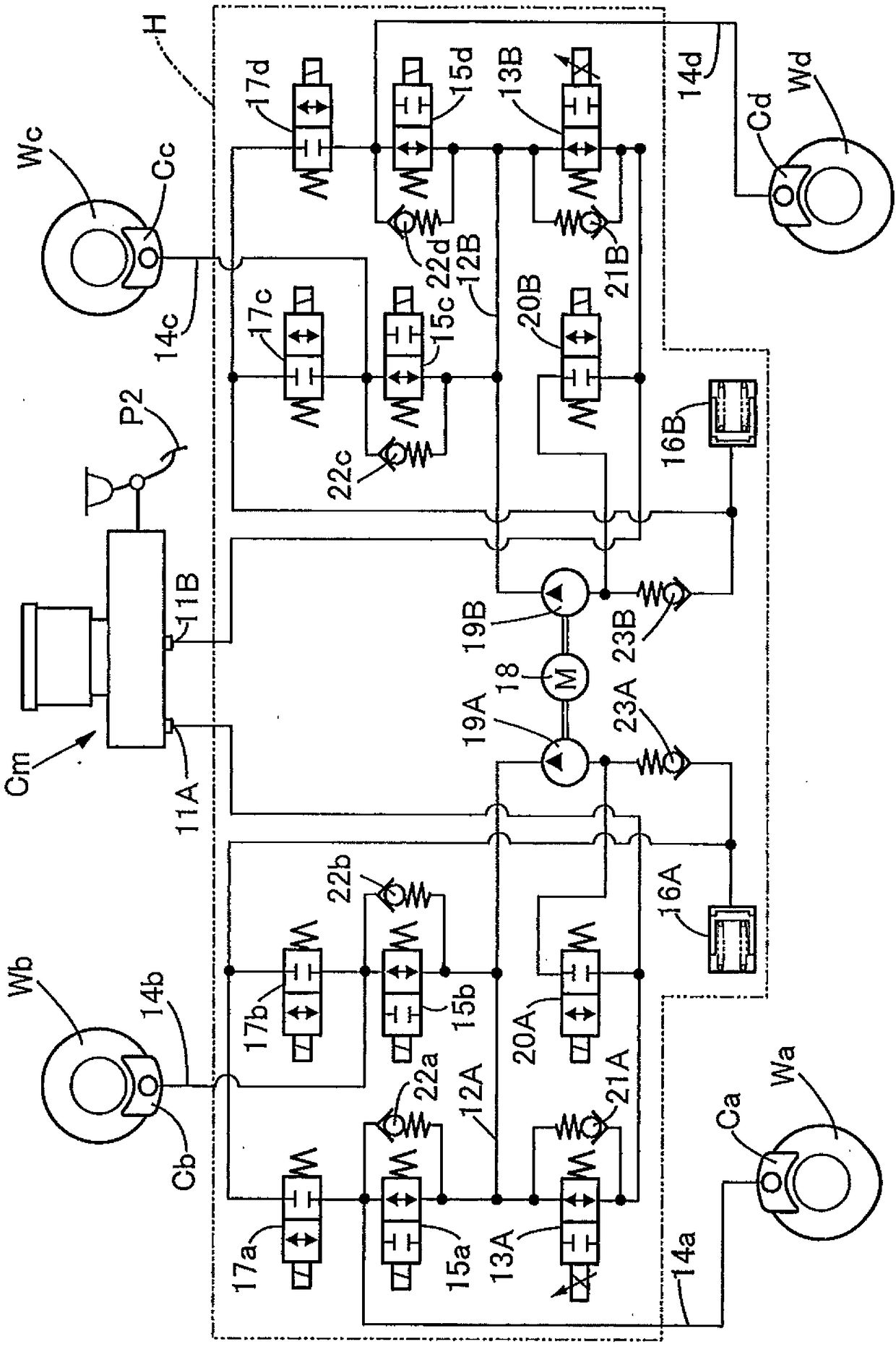
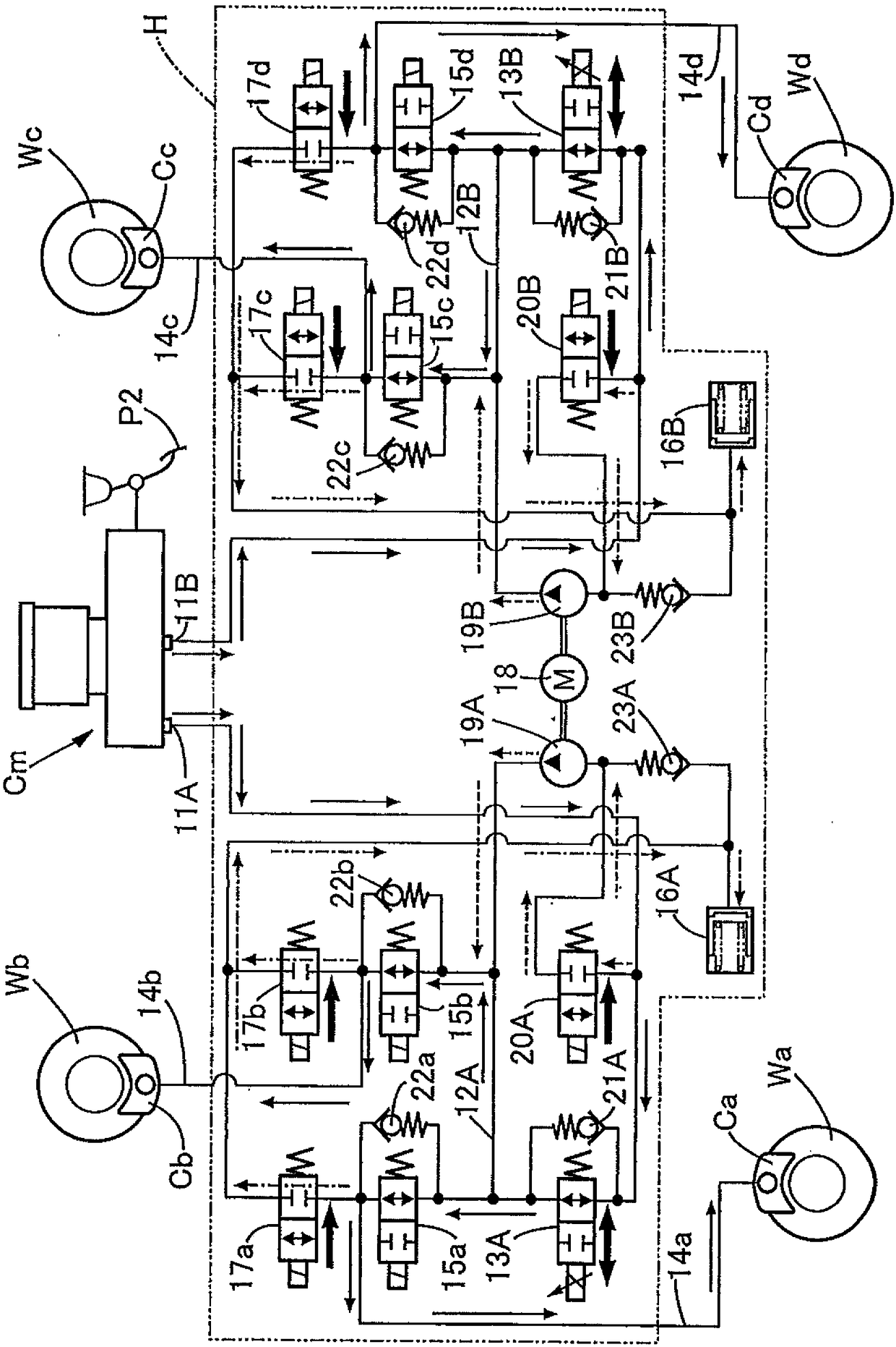
[0042] The master cylinder Cm, which is activated by the brake pedal P2 to generate brake hydraulic pressure, is connected to the left and right front wheel calipers Ca, Cc and the left and right rear wheel calipers Cd, Cb via a hydraulic regulator H incorporating an electric oil pump. . The master cylinder Cm is a boosterless type that does not have a negative pressure booster as a booster, and operates only by the driver's pedaling force input to the brake pedal P2.

[0043]The hydraul...


PUM


Abstract

An electric automobile braking device can mitigate the motion frequency of a hydraulic booster device of a master cylinder with no vacuum booster that assists the electric automobile, and can inhibitthe braking sense decline to the minimum level. The electric automobile braking device includes the master cylinder that has no vacuum booster and the hydraulic booster device that can increase a brake fluid pressure generated by the master cylinder. Switching is possible between a normal braking mode in which hydraulic braking and regenerative braking are used in combination when a percentage charge of a battery is less than a threshold value and a regenerative braking restriction mode in which hydraulic braking is permitted and regenerative braking is restricted when the battery charging percentage reaches a threshold value or greater. In the regenerative braking restriction mode, when a depressing force of a brake pedal by a driver exceeds a first depressing force over a predetermined period of time, an operation of the hydraulic booster device is suppressed, thus preventing the braking sense decline caused by excessive motions of the hydraulic booster device, the formation of motion sounds by the hydraulic booster device, and the power consumption increase of the hydraulic booster device.

Description

technical field [0001] The present invention relates to a braking device for an electric vehicle, which comprises: a master cylinder, to which the driver's brake pedal force is transmitted without being boosted, so as to generate brake hydraulic pressure; and a hydraulic booster, It can boost the brake hydraulic pressure generated by the master cylinder through the brake hydraulic pressure generated by the electric oil pump. Background technique [0002] The place where the battery of the electric vehicle is charged by an external power source is a place with high altitude, and when the battery is fully charged and driven downhill for a long time, since the battery cannot be further charged, regenerative braking of the motor cannot be performed. The potential energy originally recovered by regenerative braking is consumed in vain, and there is a problem that the cost of charging with an external power source increases. [0003] Here, according to the following patent docume...

Claims


Application Information

Patent Timeline
Patent Type & Authority Applications(China)
IPC IPC(8): B60T13/66B60L7/24B60L7/10
CPCB60L7/10B60L7/24B60T13/662B60T8/442B60T1/10B60T7/042B60T13/146B60T13/586B60T13/686F16D61/00B60T8/50B60T13/745B60T13/142
Inventor 柏井干雄田中诚井野光泰中山大
Owner HONDA MOTOR CO LTD
Why Eureka
Try Eureka