Motion compensation structure in multi-mode video decoder

A video decoder and motion compensation technology, applied in the field of multimedia video, can solve the problems of not supporting chroma interpolation, loss of image quality, failure to propose, etc., to achieve the effect of improving access efficiency and circuit throughput, and reducing bandwidth requirements

Inactive Publication Date: 2018-07-24
深圳市德赛微电子技术有限公司
View PDF5 Cites 0 Cited by
  • Summary
  • Abstract
  • Description
  • Claims
  • Application Information

AI Technical Summary

Problems solved by technology

[0003] Previous high-efficiency motion compensation circuits for H.264 / AVC all adopted a motion compensation structure based on a 4x4 fixed block size, and proposed a complex data reuse strategy and scheduling strategy to overcome the motion compensation based on a 4x4 block size. The defects brought about by these new strategies lead to the need for more on-chip memory and complex control logic to support these new strategies. At the same time, different hardware interpolation circuits are used for the brightness component and the chrominance component; the previous structure can support H.264 at the same time / AVC and AVS luma interpolation structure, but does not support chroma interpolation, and does not support other standards; some structures mainly focus on the design and implementation of motion compensation subsystem in multi-standard decoders, including motion vector prediction, etc. Does not contain a detailed description of the motion compensation interpolation structure; someone proposed to use a new 4-level directed FIR filter to replace the original 6-level filter in the H.264 / AVC standard to solve the problem of the original interpolation algorithm. Regulatory issues and excessive bandwidth requirements, but it introduces a serious loss of image quality, and also fails to propose a solution suitable for multiple standards

Method used


Image

  • Motion compensation structure in multi-mode video decoder

Examples


Embodiment Construction

[0029] It should be understood that the specific embodiments described here are only used to explain the present invention, not to limit the present invention.

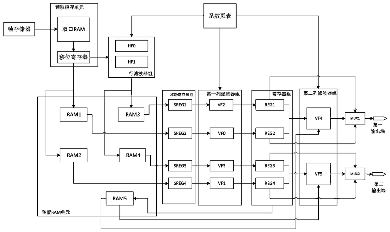
[0030] Such as figure 1As shown, this embodiment provides a motion compensation circuit compatible with multi-standard video decoders, the circuit includes a frame memory, a prefetch cache unit, a coefficient page table, an interpolation unit and an output terminal, wherein the frame memory and the prefetch cache unit connected, the interpolation unit is simultaneously connected with the prefetching cache unit, the coefficient page table and the output terminal. The frame memory is used to store the acquired image; the coefficient page table is a single-port RAM with a size of 8x64bits, which can store eight 8-tap filter coefficients, each coefficient is 8bits, and the range of filter coefficients that can be stored is [0,255]. The filter coefficients can be written externally, and the user writes different filter co...


PUM


Abstract

The invention discloses a motion compensation structure in a multi-mode video decoder. The motion compensation structure comprises a frame storage for storing a reference image; a prefetching cachingunit for reading and caching reference pixel of the external frame storage; a coefficient page table for storing a filter coefficient of a video decoder suitable for various standards; an interpolation unit comprising FIR filters capable of configuring parameters, wherein the interpolation unit is used for performing horizontal direction 1 / 2 interpolation, vertical direction 1 / 2 interpolation, horizontal direction 1 / 4 interpolation and vertical direction 1 / 4 precision interpolation filtering; an output end for outputting brightness interpolation data and chromaticity interpolation data, wherein the prefetching caching unit is connected with the frame storage; and the interpolation unit is connected with the prefetching caching unit, the coefficient page table and the output end at the sametime. By adopting the FIR filter with configurable parameter, the system can take the interpolations of both of the brightness component and the chromaticity component in various video standards intoconsideration. The invention further discloses a motion compensation method based on the system.

Description

technical field [0001] The invention relates to the technical field of multimedia video, in particular to a motion compensation structure in a multi-mode video decoder, and a motion compensation system and method that meet the decoding requirements of high-definition video on the basis of low power consumption. Background technique [0002] Motion compensation technology improves the efficiency of video coding by eliminating temporal redundancy between adjacent frames. In the latest video coding standards, motion compensation introduces many new coding techniques, including variable block size, multiple reference frames, bidirectional prediction, unrestricted motion vectors, and quarter-precision interpolation, etc. All these new technologies can improve the efficiency of video coding, but at the same time greatly increase the computational requirements and bandwidth requirements of motion compensation. In the basic level of H.264 / AVC, motion compensation occupies 25% of th...

Claims


Application Information

Patent Timeline
Patent Type & Authority Applications(China)
IPC IPC(8): H04N19/51H04N19/59H04N19/80
CPCH04N19/51H04N19/59H04N19/80
Inventor 王云刘建巴晓辉杨颖孙永刚赵星赵海棠蒋芳陈杰钟晨
Owner 深圳市德赛微电子技术有限公司
Why Eureka
Try Eureka