
Experiment device for excess pressure energy recycling and compressed air energy storage

A technology for compressed air energy storage and energy recovery, which is used in measurement devices, testing of machinery/structural components, instruments, etc. It can solve the problems of huge initial investment, long construction period, and difficulty in recovering energy, and achieve energy recovery efficiency. High, wide range of applications, flexible functions

Pending Publication Date: 2018-07-24
YULIN UNIV
View PDF5 Cites 4 Cited by
  • Summary
  • Abstract
  • Description
  • Claims
  • Application Information

AI Technical Summary

Problems solved by technology

At present, there are two kinds of energy storage technologies used for commercial operation: pumped storage and compressed air energy storage. Pumped storage technology has problems such as difficult site selection, huge initial investment, and long construction period. Compressed air energy storage technology uses compressed air Storing energy and shaving peaks and filling valleys are the current research and development hotspots of large-scale energy storage technology
However, the research and development of residual pressure energy recovery and compressed air energy storage technology and equipment at home and abroad are relatively independent, resulting in limited application of residual pressure energy recovery devices and the recovery of energy is not easy to store, while compressed air storage energy requires The contradiction of extra power consumption

Method used


Image

  • Experiment device for excess pressure energy recycling and compressed air energy storage
  • Experiment device for excess pressure energy recycling and compressed air energy storage
  • Experiment device for excess pressure energy recycling and compressed air energy storage

Examples


Embodiment Construction

[0020] The present invention will be described in further detail below in conjunction with the accompanying drawings.

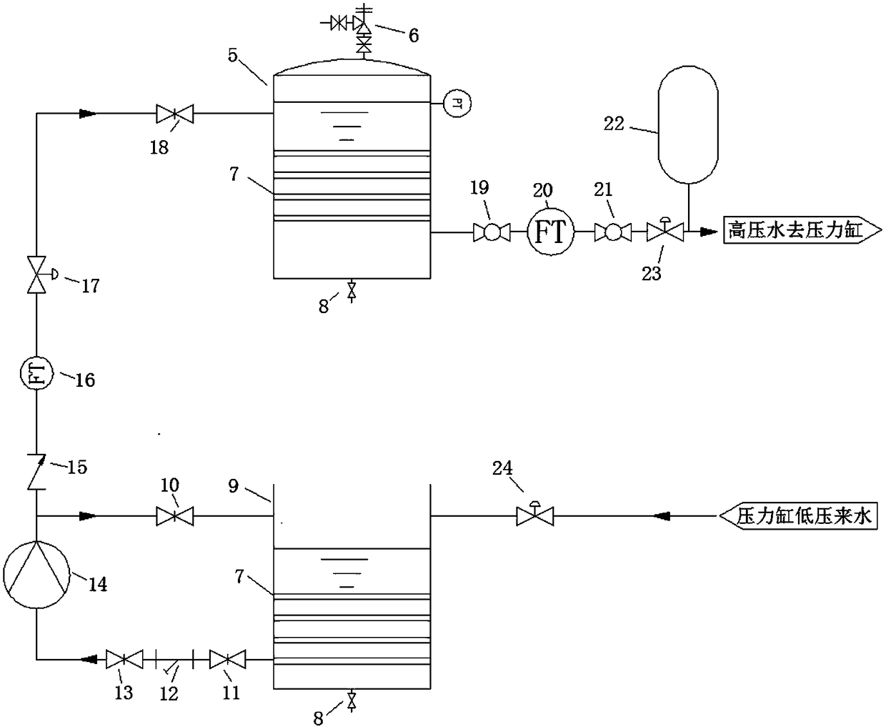
[0021] see figure 1 , the present invention structurally includes a residual pressure energy simulation module 1, a gas supply module 2, an energy replacement module 3 and an energy storage and release module 4, and the residual pressure energy simulation module 1 and the energy storage and release module 4 are respectively connected to the energy replacement module 3 ends.

[0022] see figure 2 , the residual pressure energy simulation module 2 of the present invention is provided with a high-pressure water tank 5, a safety valve 6, a steady flow grid 7, a drain valve 8, a low-pressure water tank 9, a first gate valve 10, a second gate valve 11, and a Y-type filter 12. Third gate valve 13, high pressure pump 14, first check valve 15, first flow meter 16, first regulating valve 17, fourth gate valve 18, first ball valve 19, second flow meter 20, second bal...


PUM


Abstract

The invention discloses an experiment device for excess pressure energy recycling and compressed air energy storage. The experiment device comprises an excess pressure energy simulation module and a gas supply module, wherein the gas supply module is connected with the excess pressure energy simulation module through an energy replacement module; a bidirectional pressure cylinder is arranged in the energy replacement module; a water drainage pipeline of the excess pressure energy simulation module and a gas exhaust pipeline of the gas supply module are respectively connected with two ends of the bidirectional pressure cylinder; a gas outlet of the bidirectional pressure cylinder is connected with an energy storage and release module; the energy storage and release module comprises a high-pressure air storage tank; the high-pressure air storage tank is connected with a power generator through an air turbine; the power generator is connected with a load tank. Through the energy replacement module, the excess pressure energy simulation module and the gas supply module can be combined together, fusion of an equal-pressure positive displacement energy recycling technique and a compressed air energy storage technique is achieved, technical advantages of the two techniques can be taken into play, and the experiment device has the characteristics of being high in energy recycling efficiency, convenient in storage, flexible in function, wide in application range, and the like, and has great significances for energy conservation and emission reduction.

Description

technical field [0001] The invention relates to energy recovery technology, in particular to an experimental device for residual pressure energy recovery and compressed air energy storage. Background technique [0002] The residual pressure energy recovery device can be used to recover the energy of high-pressure liquid to achieve the purpose of energy saving and emission reduction. The residual pressure energy recovery device is mainly divided into centrifugal type and positive displacement type according to its working principle. The centrifugal hydraulic booster represented by HPB needs to undergo the conversion of "pressure energy→mechanical energy→pressure energy". The requirements are relatively strict and the recovery efficiency is relatively low; while the positive displacement energy recovery device represented by the piston power exchanger only needs to undergo the transformation of "pressure energy → pressure energy", theoretically there is no energy conversion lo...

Claims


Application Information

Patent Timeline
IPC IPC(8): G01M99/00
CPCG01M99/005
Inventor 毕智高杨军虎罗凯凯王金玺逄仁刚贾冰王永越韩宾王伟石念军
Owner YULIN UNIV
Learn More