
Overall-prefabricated main transformer foundation and oil pit structure used for indoor substation

An integral prefabrication and substation technology, applied in infrastructure engineering, protective devices, buildings, etc., can solve the problems of no related technology in assembly, difficulty in pouring, and difficulty in supporting formwork, so as to save concrete volume, strong bearing capacity, and stable structure good sex effect

Pending Publication Date: 2018-07-24
SHANGHAI ELECTRIC POWER DESIGN INST
View PDF4 Cites 4 Cited by
  • Summary
  • Abstract
  • Description
  • Claims
  • Application Information

AI Technical Summary

Problems solved by technology

The whole process is complicated, and at the same time, due to the small distance between the pier and beams of the main transformer foundation, the operation is difficult, resulting in difficulty in supporting the formwork, difficulty in pouring, and a long construction period
[0004] At present, there are many patents on the prefabricated main transformer foundation as an independent main transformer foundation. This kind of foundation is suitable for outdoor substations. There is no related technology for the combination of indoor substations and basement foundations and overall assembly with oil pits.

Method used


Image

  • Overall-prefabricated main transformer foundation and oil pit structure used for indoor substation
  • Overall-prefabricated main transformer foundation and oil pit structure used for indoor substation
  • Overall-prefabricated main transformer foundation and oil pit structure used for indoor substation

Examples


Embodiment

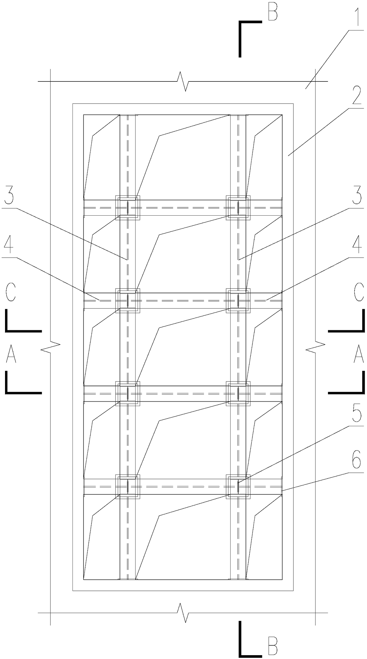
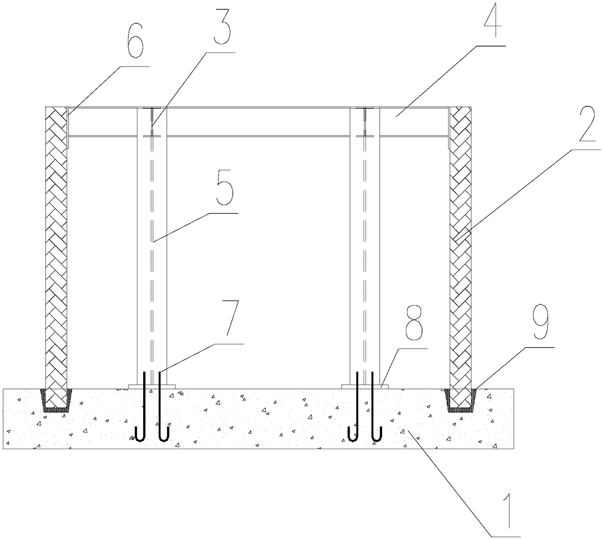
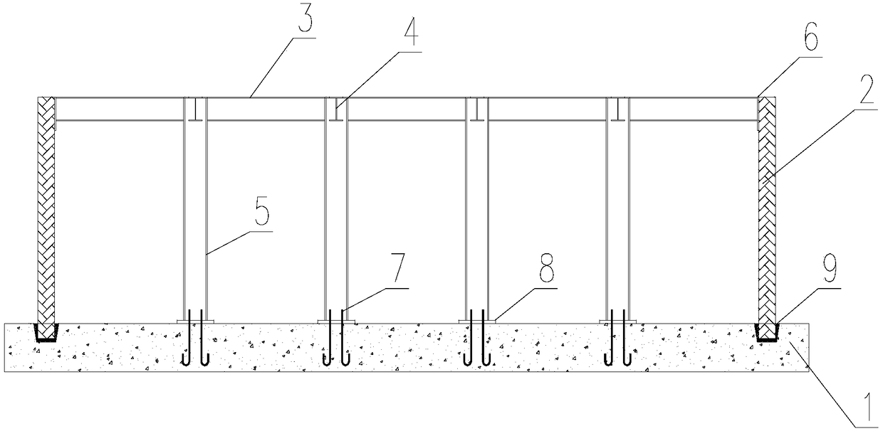
[0025] refer to figure 1 , figure 2 , image 3 , the present invention includes a cast-in-place building overall raft foundation 1, the position of the main transformer is set on the building raft foundation 1, and the anchor bolts 7 arranged in a matrix are pre-embedded. Four rows of anchor bolts 7 are pre-embedded in the direction, and two anchor bolts 7 are arranged in each row. Backing plate 8 is set on described anchor bolt 7, and foundation pile 5 is set on described backing plate 8, and the top of described foundation pile 5 connects beam 4, and the column top of described foundation pile 5 is along the length direction of building raft 1 foundation The track beam 3 is installed by welding, and the track beam 3 adopts an I-shaped steel beam. The track beam 3 and the crossbeam 4 are vertically arranged, and the oil pit wall groove is preset on the building raft foundation 1 around the main transformer, and the oil pit wall 2 is placed in the groove, and the oil pit w...


PUM


Abstract

The invention relates to an overall-prefabricated main transformer foundation and oil pit structure used for an indoor substation. The overall-prefabricated main transformer foundation and oil pit structure comprises a cast building raft foundation. Matrix-arranged foundation bolts are pre-embedded in the position, where a main transformer is arranged, on the building raft foundation; foundation piles are arranged on the foundation bolts, and the tops of the foundation piles are connected with crossbeams; the column tops of the foundation piles are provided with rail beams in the length direction of the building raft foundation, and the rail beams and the crossbeams are perpendicularly arranged; oil pit wall clamping grooves are pre-formed in the position, around the main transformer, of the building raft foundation; and oil pit walls are placed in the clamping grooves, and the tops of the oil pit walls are connected with the crossbeams and the rail beams. An overall splicing technology of the main transformer foundation is adopted, and the defects of cast-in-place construction of a traditional main transformer foundation are overcome; the construction period of a main transformerfoundation item project can be shortened greatly, the construction efficiency is improved, and a frame system is good in structural stability and high in bearing capacity; and the oil pit oil-leakageprobability is decreased greatly by adopting a novel prefabricated wallboard splicing technology.

Description

technical field [0001] The invention belongs to the technical field of substation main transformer foundations, and in particular relates to an integral prefabricated main transformer foundation and an oil pit structure for indoor substations. Background technique [0002] The whole indoor substation usually has a main transformer on the first floor. Due to the heavy weight of the transformer, it usually cannot be placed directly on the floor, and a separate foundation is required. Indoor substations usually have a basement, and the main transformer foundation is placed in the basement, which is integrated with the basement floor or the raft foundation of the entire building. [0003] Under the existing technical conditions, the basement part of the substation usually adopts the cast-in-place concrete structure. The main transformer foundation also adopts cast-in-place concrete structure. The foundation of the main transformer needs to meet the requirements of equipment pl...

Claims


Application Information

Patent Timeline
Patent Type & Authority Applications(China)
IPC IPC(8): E02D27/44E02D31/02
CPCE02D27/44E02D31/02
Inventor 陈轩彭益成
Owner SHANGHAI ELECTRIC POWER DESIGN INST
Learn More