Al technical title is built by PatSnap Al team. It summarizes the technical point description of the patent document.
A feeding machine and mobile technology, applied in the direction of conveyors, conveyor objects, animal feeding devices, etc., can solve the problems of increased cost, complicated operation, high work intensity, etc., to achieve reduced work intensity, uniform material transmission, and reduced The effect of attrition
Pending Publication Date: 2018-07-24
ZHANGZHOU TIANYANG MACHINERY
View PDF16 Cites 9 Cited by
Summary
Abstract
Description
Claims
Application Information
AI Technical Summary
This helps you quickly interpret patents by identifying the three key elements:
Problems solved by technology
Method used
Benefits of technology
Problems solved by technology
[0002] At present, most of the feeding animals in the farms are mainly fed artificially, which requires a lot of manpower and time, and the work intensity is high and the work efficiency is low. It needs to use a feeder to do the work, but the feeder used on the market cannot Accurately control the amount of materials added each time, resulting in unbalanced growth, and some materials are easy to agglomerate when they accumulate for a long time. The feeder cannot stir these accumulated materials, and the staff have to stir them to disperse them and increase them. Manpower consumption increases costs, and these feeders are inconvenient to move, complicated to operate, and not practical enough
Method used
Image
Click on the blue label to locate the original text in one second.
Reading with bidirectional positioning of images and text.
Examples
Embodiment Construction
[0018] The following will clearly and completely describe the technical solutions in the embodiments of the present invention with reference to the accompanying drawings in the embodiments of the present invention. Obviously, the described embodiments are only some, not all, embodiments of the present invention. Based on the embodiments of the present invention, all other embodiments obtained by persons of ordinary skill in the art without making creative efforts belong to the protection scope of the present invention.
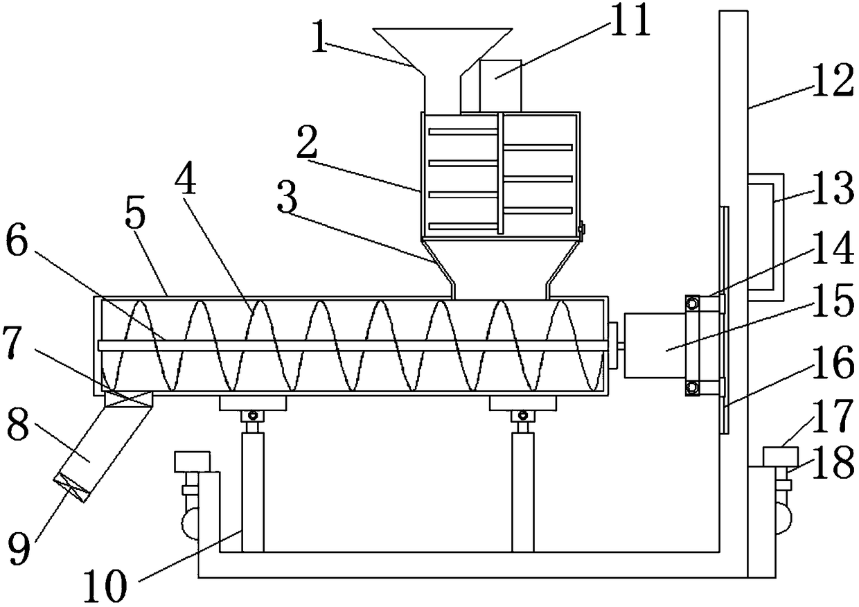
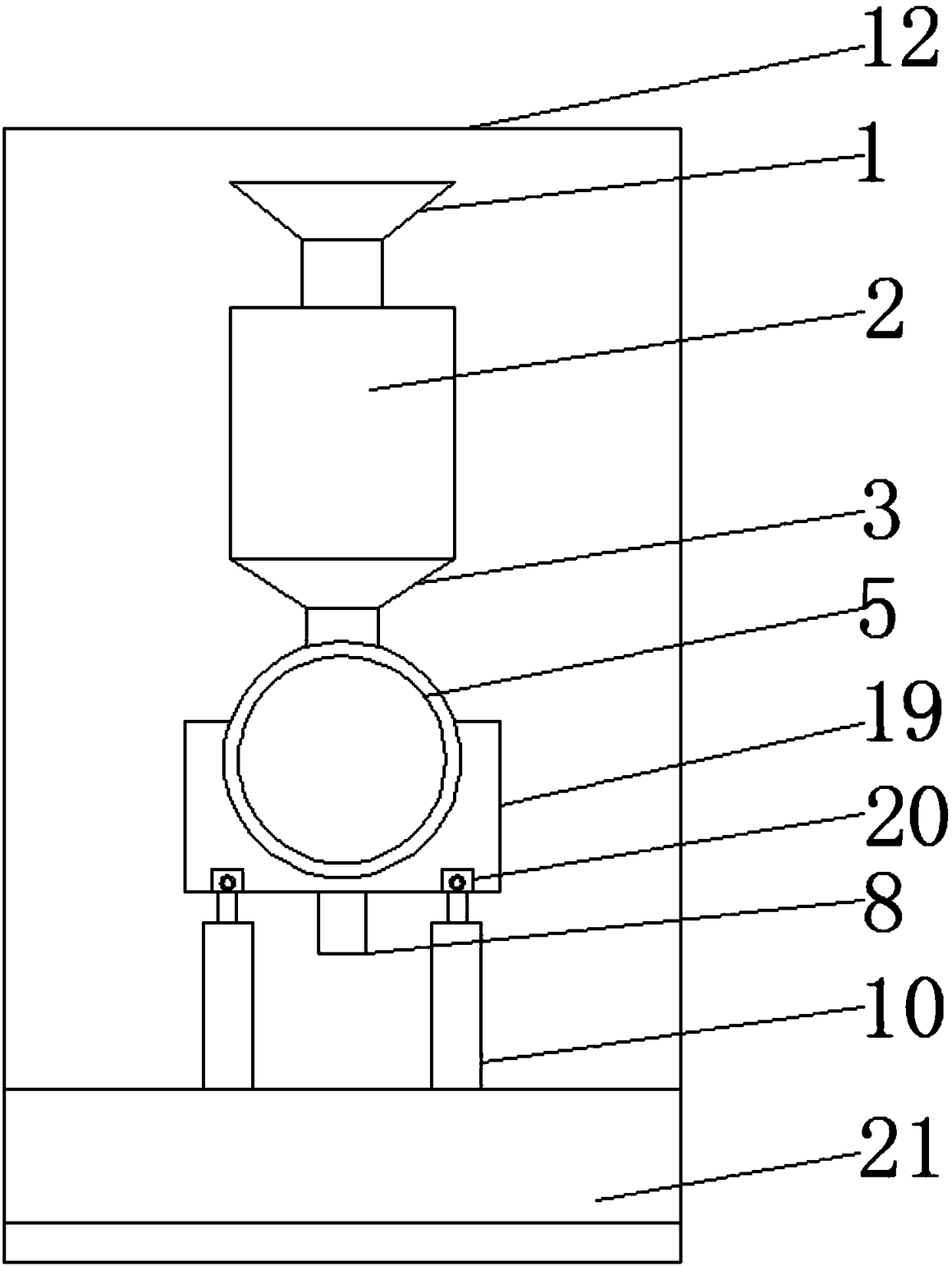
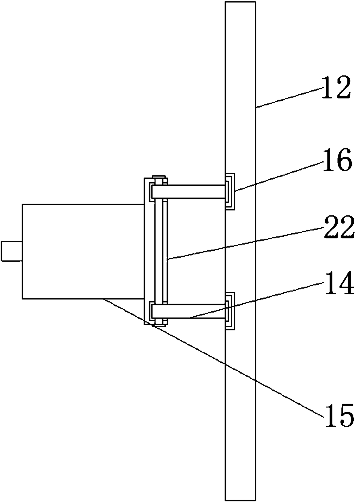
[0019] see Figure 1~5 , in an embodiment of the present invention, a mobile feeder includes a feed hopper 1, a stirring box 2, a feed hopper 3, a spiral blade 4, a main shaft 5, a feed box 6, a feed valve 7, a feed pipe 8, Discharge valve 9, hydraulic cylinder 10, first motor 11, bracket 12, handrail 13, connecting rod 14, second motor 15, guide rail 16, moving wheel 17, pole 18, fixed seat 19, fixed part 20, baffle 21. Support plate 22, sealing insert plate...
PUM
Abstract
The invention discloses a movable charging machine which comprises a feeding hopper, a stirring box, a guide hopper, a spiral blade, a main shaft, a guide box, a feeding valve, a guide pipe, a discharge valve, a hydraulic cylinder, a first motor, a support, a handrail, a connection rod, a second connection rod, a guide rail, moving wheels, a supporting rod, a fixed base, a fixed portion, a baffle,a supporting plate, a sealing plug plate, a fixing pin, a pull plate and a sealing slot. The material adding amount is controlled through the feeding valve, the guide pipe and the discharge valve, quantitative charging is achieved, the hydraulic cylinder and the fixed base are hinged, the inclination angle of the guide box and the guide pipe is flexibly adjusted, materials can be guided out moreeasily, and device moving is convenient through the moving wheels. Moving is convenient, fixing is stable, quantitative charging can be achieved, material conveying is more uniform, operation is easy,the work intensity is lowered, personnel loss is reduced, the cost is saved, and practicability is good.
Description
technical field [0001] The invention relates to the field of feeders, in particular to a mobile feeder. Background technique [0002] At present, most of the feeding animals in the farms are mainly fed artificially, which requires a lot of manpower and time, and the work intensity is high and the work efficiency is low. It needs to use a feeder to do the work, but the feeder used on the market cannot Accurately control the amount of materials added each time, resulting in unbalanced growth, and some materials are easy to agglomerate when they accumulate for a long time. The feeder cannot stir these accumulated materials, and the staff have to stir them to disperse them and increase them. Manpower consumption increases costs, and these feeders are inconvenient to move, complicated to operate, and not good enough in practicability. Contents of the invention [0003] The purpose of the present invention is to provide a mobile feeder to solve the problems raised in the above-...
Claims
Application Information
Patent Timeline
Application Date:The date an application was filed.
Publication Date:The date a patent or application was officially published.
First Publication Date:The earliest publication date of a patent with the same application number.
Issue Date:Publication date of the patent grant document.
PCT Entry Date:The Entry date of PCT National Phase.
Estimated Expiry Date:The statutory expiry date of a patent right according to the Patent Law, and it is the longest term of protection that the patent right can achieve without the termination of the patent right due to other reasons(Term extension factor has been taken into account ).
Invalid Date:Actual expiry date is based on effective date or publication date of legal transaction data of invalid patent.