Cleaning device for mechanical part

A technology for cleaning devices and mechanical parts, applied in the direction of dryers, drying gas arrangements, cleaning methods and appliances, etc., can solve the problems of wasting cleaning liquid, high cleaning power of parts, and cost waste, so as to reduce cost waste and improve cleaning quality. High, good cleaning effect

Inactive Publication Date: 2018-07-24
DONGGUAN KAILEDI NUMERICAL CONTROL SCI & TECH CO LTD
View PDF0 Cites 8 Cited by
  • Summary
  • Abstract
  • Description
  • Claims
  • Application Information

AI Technical Summary

Problems solved by technology

However, the existing mechanical parts cleaning device has the disadvantages of uneven and incomplete washing on the surface of the parts, and in the process of cleaning the parts, it cannot perform proper washing according to the degree of dirt accumulation on the parts themselves, so that the parts with less stains can be cleaned If the force is too high, more cleaning fluid will be wasted, and parts with a lot of dirt cannot achieve a good cleaning effect due to the low cleaning force; the existing mechanical parts cleaning equipment is used to wash the parts after cleaning. Generally, recycling is not carried out, resulting in a large amount of cost waste; and when the existing mechanical parts cleaning equipment cleans the parts, most of them put the parts into the barrel and wash them directly, not only cannot clean the parts from multiple angles, but also It is not easy to wash, and the cleaning effect is poor; and when the parts are piled up and washed, the middle parts are difficult to clean, and the efficiency of cleaning a single part is extremely low; because some parts have pores in the structure, most of the existing mechanical parts cleaning equipment is Put the parts on the filter plate for scouring, without moving and rotating the parts during scouring, it is difficult to clean the gaps of the parts; and after cleaning the parts, the residual dirt on the filter plate enters the holes of the filter plate, which is inconvenient Cleaning is inconvenient to use; moreover, the existing cleaning equipment for mechanical parts only has the function of cleaning and cannot dry the cleaned parts, and the parts are more likely to be rusted, damaged or re-contaminated with dirt during transportation ; The existing mechanical parts cleaning equipment has low efficiency and poor cleaning effect, which is very impractical and unreliable

Method used


Image

  • Cleaning device for mechanical part
  • Cleaning device for mechanical part
  • Cleaning device for mechanical part

Examples


Embodiment Construction

[0033] Below in conjunction with accompanying drawing and specific embodiment the present invention is described in further detail:

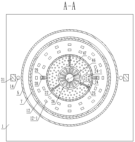
[0034] Such as Figure 1-Figure 9 As shown, a mechanical parts cleaning device includes a base plate 1, a support column A2 is symmetrically fixed on the top surface of the base plate 1, a water tank 3 is fixed on the top surface of the support column A2, and the top surface of the water tank 3 The surface welding is fixed with the cone tube A4 integrally formed with it, the top surface of the cone tube A4 is welded and fixed with the sleeve A5 integrally formed with it, the inside of the cone tube A4 is provided with a cone tube B6, and the inside of the cone tube B6 The side is evenly provided with a plurality of square through holes A6-1, the inside of the sleeve A5 is provided with a sleeve B7, and the side of the sleeve B7 is evenly provided with a plurality of square through holes B7-1, the cone A4 and the cone The bottom surfaces of the ...


PUM


Abstract

The invention discloses a cleaning device for a mechanical part. The cleaning device comprises a bottom plate, supporting column bodies A are symmetrically fixed to the top surface of the bottom plate; a water tank is arranged on the top surfaces of the supporting column bodies A, the top surface of the water tank is welded with a cone cylinder A which is integrally formed with the water tank, anda sleeve A which is integrally formed with the cone cylinder A is welded and fixed on the top surface of the cone cylinder A; a cone cylinder B is arranged in the cone cylinder A, and multiple squarethrough holes A are uniformly formed in the side surface of the cone cylinder B; a sleeve B is arranged in the sleeve A, multiple square through holes B are uniformly formed in the side surface of the sleeve B; and the conical cylinder A is fixedly connected to the bottom surface of the conical cylinder B through an annular plate A. According to the cleaning device, the part can be cleaned from all directions, the surface of the part is washed more uniformly and thoroughly, and the multiple parts can be washed at one step, the cleaning efficiency is high, a proper amount of flushing can be performed according to the dirt accumulation degree of the part, so that the good cleaning effect is achieved; and meanwhile, the probability that the part is rusted, damaged or stained again in the transportation process is reduced, and the cleaning device is high in use efficiency and is very practical and reliable.

Description

technical field [0001] The invention relates to the field of mechanical equipment, in particular to a cleaning device for mechanical parts. Background technique [0002] Mechanical parts will generate dirt during processing or after being placed for a period of time. The parts need to be cleaned before they can be used for mechanical equipment assembly and installation. Generally, the dirt on parts comes from the residual molding sand or dust in the casting process, or If the residual cutting fluid, oil and other dirt in the process of storage and transportation are not cleaned, it will make it difficult to guarantee the assembly quality. Defects in the cleaning process, deformation and damage caused during transportation and storage can also be found and dealt with in time during the cleaning process. However, the existing mechanical parts cleaning device has the disadvantages of uneven and incomplete washing on the surface of the parts, and in the process of cleaning the ...

Claims


Application Information

Patent Timeline
Patent Type & Authority Applications(China)
IPC IPC(8): B08B3/02B08B3/14B08B3/10B08B1/02F26B21/00B08B1/20
CPCF26B21/00B08B3/02B08B3/044B08B3/14B08B1/12B08B1/20
Inventor 郭良山
Owner DONGGUAN KAILEDI NUMERICAL CONTROL SCI & TECH CO LTD
Why Eureka
Try Eureka