Immersed membrane separation device and operating method thereof

A submerged and separation membrane technology, applied in the field of membrane separation, can solve the problems of insufficient and serious friction between membrane filaments, accumulation of membrane filament sludge, etc., and achieve low pollution, high energy consumption, and low energy consumption.

Inactive Publication Date: 2018-07-24
TIANJIN POLYTECHNIC UNIV
View PDF1 Cites 3 Cited by
  • Summary
  • Abstract
  • Description
  • Claims
  • Application Information

AI Technical Summary

Problems solved by technology

However, the upper end of the membrane filaments only moves up and down, which is not strong enough for the mutual friction between the membrane filaments.
In the patent application "A Submerged Hollow Fiber Membrane Module Serpentine Lifting Operation Method" filed by the inventor with the application number 2015106

Method used


Image

  • Immersed membrane separation device and operating method thereof
  • Immersed membrane separation device and operating method thereof
  • Immersed membrane separation device and operating method thereof

Examples


Embodiment 1

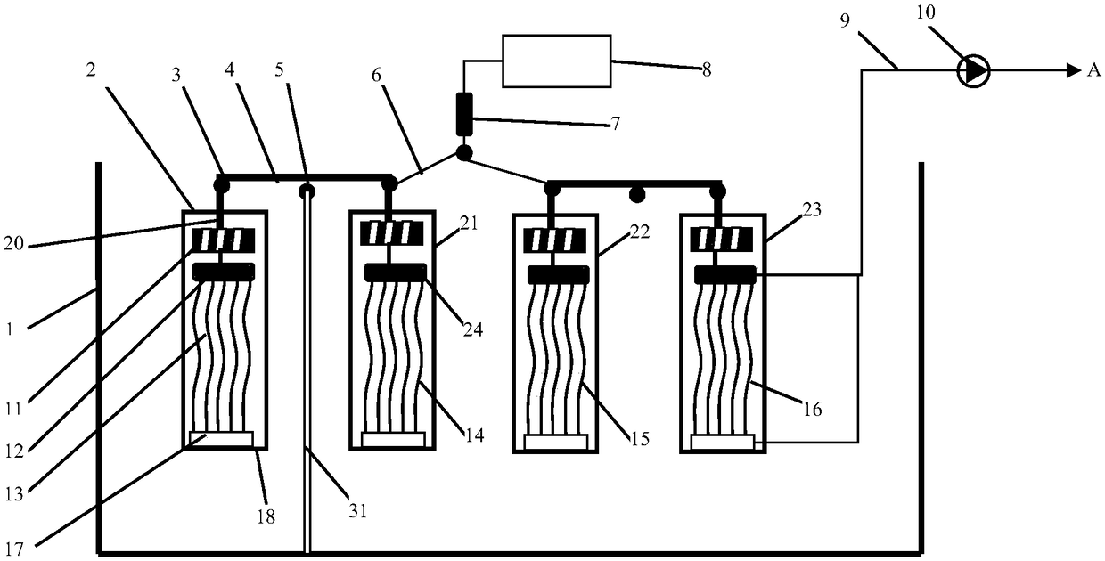
[0030] Embodiment one, such as figure 1 Shown: there are multiple membrane unit frames, shown as the first membrane frame 2, the second membrane frame 21, the third membrane frame 22, and the fourth membrane frame 23, which are respectively immersed in the water tank 1; The two cantilever ends are respectively connected to the upper ends 12, 24 of the membrane unit 13 and the membrane unit 14 through the rotatable connector 3 to form a balance group; 5 is the gravity balance fulcrum of the balance bar, fixed on the bracket 31; Another balance bar connects the membrane unit 15 and the membrane unit 16 to form another balance group; the two balance groups form a linkage group through the linkage rope 6 and the traction component 7 and the traction motor 8 . The improvements are: cancel the high energy consumption blower configuration of the prior art, and instead set the traction motor, the bracket 31 is vertically fixed in the water tank, can also be installed horizontally on t...

Embodiment 2

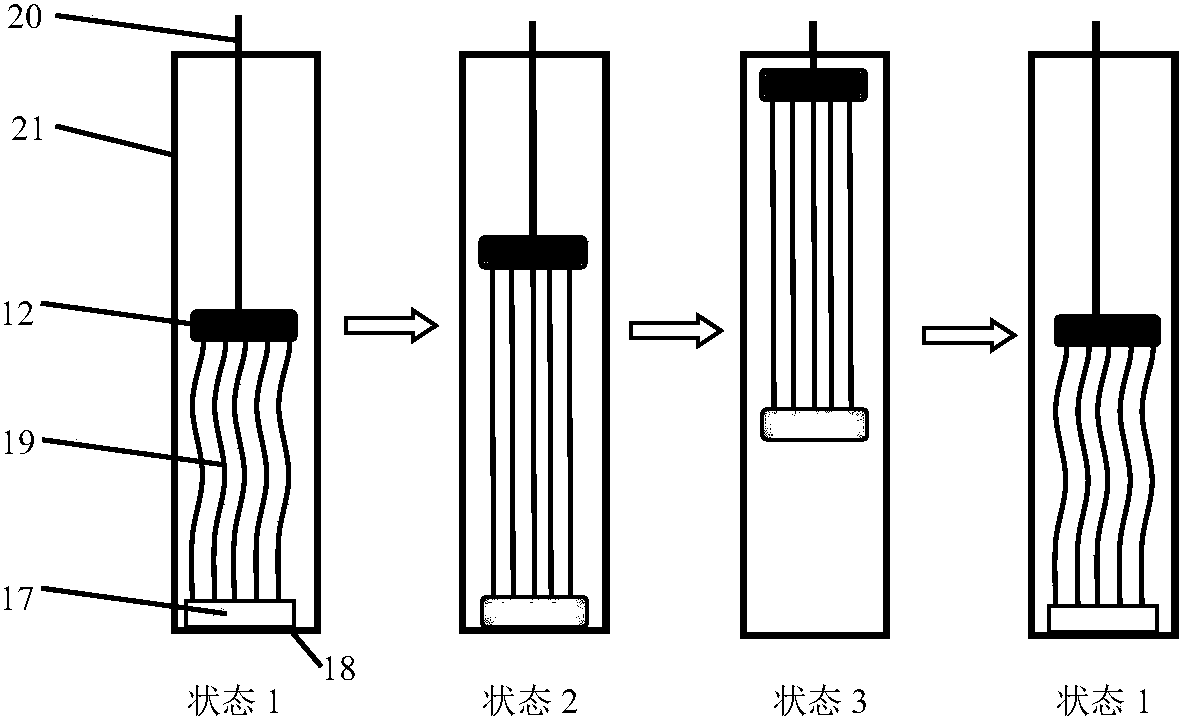
[0034] Embodiment two, such as image 3 As shown, the membrane filaments 19 in the membrane unit are pre-fixed by the pull rod 41 and are in a forced bending state. The bending degree of the membrane filament is represented by the bending amount of the membrane filament. The bending amount of the membrane filament is the maximum swing amplitude of the lateral swing displacement of the membrane filament at the half length of the membrane filament in the longitudinal direction of the membrane unit. In this embodiment, the bending amount of the membrane wire is preset to be 20 cm. When the upper end 12 of the membrane unit 13 is lifted by the traction rope 20, under the linkage action of the pull rod 41, the membrane unit as a whole is lifted from the low position 1 to the high position. 2. After the traction is stopped, the membrane unit 13 sinks under the gravity of the balance weight, and when the lower end 17 of the membrane unit sinks to the limited position 18, it returns t...


PUM


Abstract

The invention relates to an immersed membrane separation device and an operating method thereof. By virtue of the mechanical lifting action and the natural gravity sinking action of a traction motor,a membrane unit positioned in a membrane frame periodically moves up and down; and by virtue of the contact shear action of membrane filament surfaces and water, the effect of controlling membrane pollution is achieved, so that the membrane separation device can stably operate for a long term. The membrane unit has two movement modes: (1) the upper end and the lower end of the membrane unit do notsynchronously rise or sink, and hollow fiber membrane filaments are periodically loosened or tightened; and (2) the upper end and the lower end of the membrane unit are fixed at a mutual distance through a pull rod or a rope, the membrane filaments are kept to be in a certain loosened state, and the whole membrane unit synchronously moves up and down for a certain distance. The immersed membraneseparation device and the operating method thereof provided by the invention can be applied to aerobic membrane bioreactors, anaerobic membrane bioreactors and membrane chemical reactors.

Description

technical field [0001] The invention belongs to the field of membrane separation, and relates to a submerged membrane separation device and an operating method thereof, in particular to a submerged membrane separation device and an operating method thereof for membrane pollution control in the membrane separation process. Background technique [0002] The existing membrane bioreactor is the product of the combination of the traditional activated sludge method and the emerging membrane separation technology. It uses the membrane separation module to replace the secondary sedimentation tank in the traditional process, which can not only greatly reduce the floor area, but also The efficiency of solid-liquid separation is significantly improved, and the quality of effluent water is significantly improved. Membrane chemical reactor is the integration of chemical reaction process and membrane separation process, such as the integration of chemical flocculation and membrane separat...

Claims


Application Information

Patent Timeline
IPC IPC(8): B01D63/00B01D65/08C02F3/12C02F3/28
CPCB01D63/00B01D65/08C02F3/1273C02F3/2853Y02W10/10
Inventor 吕晓龙陈倩倩马忠
Owner TIANJIN POLYTECHNIC UNIV
Why Eureka
Try Eureka