Reverse micro-pore forming apparatus for corneas

A device and micropore technology, which is applied in the field of medical devices, can solve the problems of corneal reverse micropore maker, the inability to accurately control the depth of tearing, and the unevenness of the tearing surface, so as to avoid irregular incision margins , easy processing, high economic benefits

Pending Publication Date: 2018-07-24
SHANGHAI TONGJI HOSPITAL
View PDF2 Cites 0 Cited by
  • Summary
  • Abstract
  • Description
  • Claims
  • Application Information

AI Technical Summary

Problems solved by technology

The difference from the present invention is that the above-mentioned utility model is designed for tearing off the elastic layer of the cornea. If it is directly used to reversely peel off the turbid post-plantation lamellar layer after lamellar keratoplasty, not only cannot accurately control the depth of tearing, but also consumes Time-consuming and labor-intensive, it is easy to cause unevenness or even aggravation of turbidity on the tear-off surface
[0008] But there is no report about a kind of corneal reverse micropore maker of the present invention

Method used


Image

  • Reverse micro-pore forming apparatus for corneas
  • Reverse micro-pore forming apparatus for corneas
  • Reverse micro-pore forming apparatus for corneas

Examples


Embodiment 1

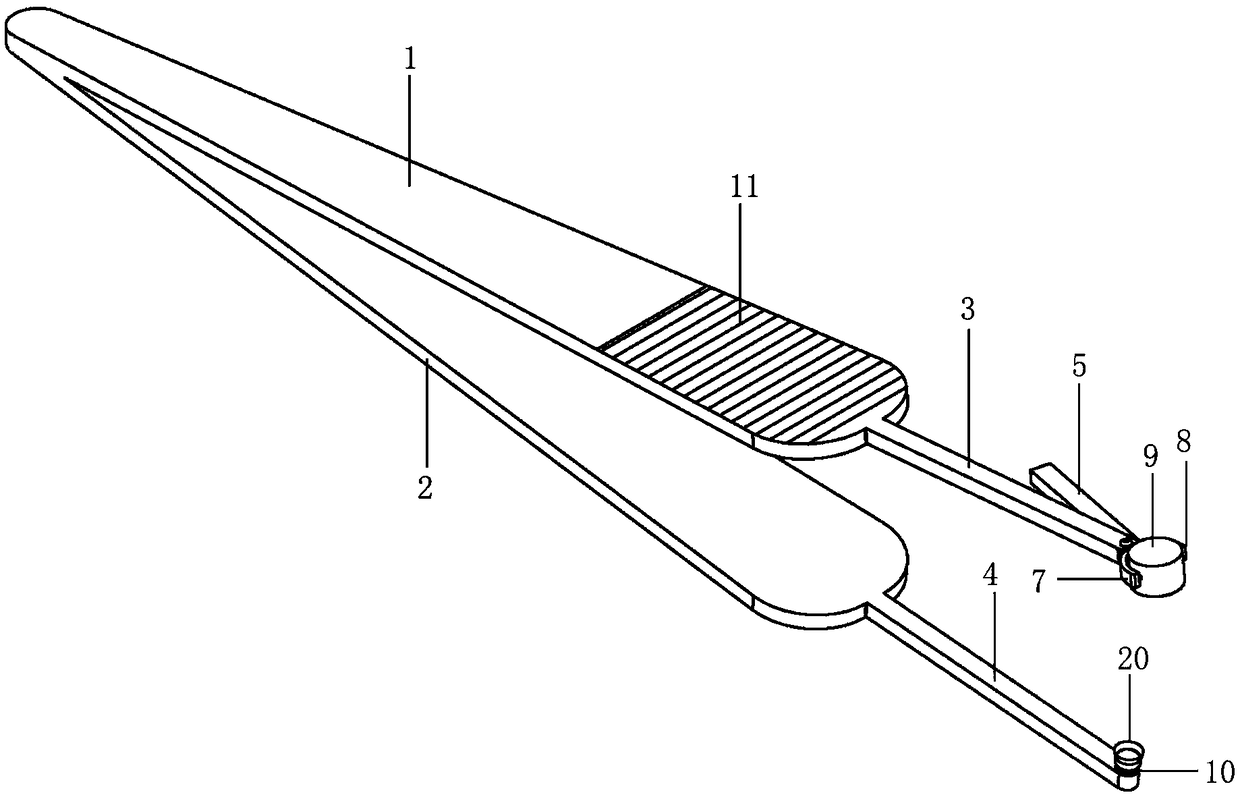
[0060] Please refer to the attached figure 1 , with figure 1 It is a structural schematic diagram of a corneal reverse micropore maker in this embodiment. The corneal reverse microhole maker includes an upper handle (1), a lower handle (2), an upper extension rod (3), a lower extension rod (4), an adjustment rod (5), a torsion spring (6), an extension rod Fixed ring (7), adjusting rod fixed ring (8), gasket (9), depth control shaft (10) and punch (20);

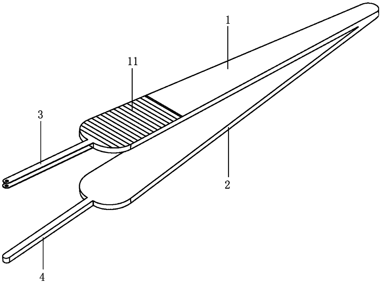
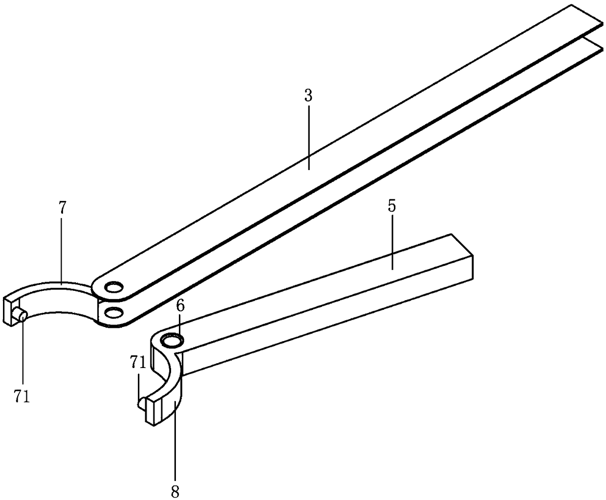
[0061] Please refer to the attached figure 2 , attached image 3 , attached Figure 8 , with figure 2 It is a schematic diagram of the combination of the upper end handle, the lower end handle, the upper end extension rod, and the lower end extension rod of a kind of corneal reverse micropore maker in this embodiment. image 3 It is a schematic diagram of the combination of the upper extension rod and the extension rod fixing ring, the adjustment rod and the adjustment rod fixing ring of a corneal reverse microhole mak...

Embodiment 2

[0066] Please refer to the attached figure 1 , attached Figure 9 , with figure 1 It is a schematic structural view of a corneal reverse micropore maker in this embodiment, with Figure 9 It is a plan view of the use of a corneal reverse micropore maker in this embodiment.

[0067] The use process and method of the corneal reverse micropore maker:

[0068] The center of the visual axis of the patient's eye was marked before the operation, and the interface between the graft and the implant bed was determined by OCT, and the thickness from the interface to the corneal endothelial surface was measured. Adjust the drilling depth.

[0069] When the depth control shaft (10) and the punch (20) are completely screwed together, the upper end of the latter is 10 μm higher than the former; according to the required depth, each time the punch (20) is screwed out one turn, the punch (20) moves up 20 μm. During the operation, positioning marks were made on the outer surface of the co...


PUM


Abstract

The invention relates to a reverse micro-pore forming apparatus for corneas. The reverse micro-pore forming apparatus comprises an upper-end handle, a lower-end handle, an upper-end extension rod, a lower-end extension rod, an adjusting rod, a torsion spring, an extension rod fixing ring, another extension rod fixing ring, a gasket, a depth control shaft and a punch. The reverse micro-pore formingapparatus for the corneas has the advantages that the reverse micro-pore forming apparatus can cling to the human corneas, circumferential resection can be pertinently quickly carried out on turbid portions of posterior lamellar layers of optical zones of the corneas under direct vision on the premise that anterior layers of the corneas are not injured, accordingly, follow-up stripping can be facilitated, and the problem of impaired vision due to donor graft turbidity of lamellar corneal transplantation postoperative optical zones can be solved; implants can be prevented from being involved by lamellar corneal transplantation postoperative primary focus relapse to a certain extent, and the utilization rate of medical resources can be increased.

Description

technical field [0001] The invention relates to the technical field of medical instruments, in particular to a corneal reverse microhole maker. Background technique [0002] Corneal disease is one of the major blinding eye diseases in my country, and corneal transplantation, as an organ transplant with the highest success rate, is an important means of treatment and vision restoration. Since the development of keratoplasty, there have been a variety of surgical methods to choose from. Compared with traditional penetrating keratoplasty (that is, replacing the full-thickness recipient cornea with a healthy donor cornea), lamellar keratoplasty is After resection of the recipient corneal diseased tissue, transplanting a transparent donor lamellar corneal graft with a corresponding thickness has the advantages of relatively low requirements for donor corneal materials, fewer surgical complications, and less chance of rejection; however, postoperative recurrence The high rate and...

Claims


Application Information

Patent Timeline
Patent Type & Authority Applications(China)
IPC IPC(8): A61F9/007
CPCA61F9/007
Inventor 毕燕龙林慧牛国桢张娟郑昌月黄心瑜
Owner SHANGHAI TONGJI HOSPITAL
Why Eureka
Try Eureka