
a food processor

A technology of food processing machine and crushing chamber, which is applied in the direction of kitchen utensils, household utensils, applications, etc., and can solve the problems of low rebound force of materials, increase of consumer cleaning net cover, poor crushing, etc.

Active Publication Date: 2021-12-03
JOYOUNG CO LTD
View PDF9 Cites 0 Cited by
  • Summary
  • Abstract
  • Description
  • Claims
  • Application Information

AI Technical Summary

Problems solved by technology

[0002] The existing soymilk machine includes a machine head and a cup body. The machine head is located in the cup body, and the cup body is generally in the shape of a straight barrel, and the diameter of the cup body is much larger than the rotation diameter of the crushing blade. Therefore, In the process of pulping, the crushing blade drives the material to rotate at a high speed, and the material will move away from the crushing blade under the action of centrifugal force, which causes the phenomenon that the material cannot be crushed by the crushing blade
Even when the material hits the cup wall at high speed by the centrifugal force, it will rebound towards the crushing blade. However, because the distance between the cup wall and the crushing blade is relatively long, the energy of the material particles will be weakened instantly after hitting the cup wall, resulting in a small rebound force of the material. , and under the blocking effect of the centrifugal force of the slurry, the bounced material cannot be collided by the crushing blade, which is likely to cause poor crushing and affect the taste of soy milk drinks
Based on this, most of the existing soymilk machines need to use the net cover to crush the materials, which not only increases the cost of the whole soymilk machine, but also increases the difficulty for consumers to clean the net cover

Method used


Image

  • a food processor
  • a food processor
  • a food processor

Examples


Embodiment 1

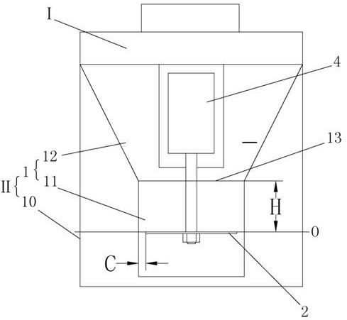
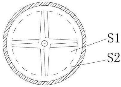
[0037] Such as figure 1 , figure 2 Shown is a schematic structural diagram of the first embodiment of the present invention. A food processing machine, the crushing device of the food processing machine includes a container 1, the crushing blade 2 is driven by a motor 4, the container 1 includes a crushing chamber 11 at the bottom of the container, and a mixing chamber above the crushing chamber 11 12 and the converging port 13 connecting the crushing chamber 11 and the mixing chamber 12, the crushing chamber 11 is provided with a crushing blade 2, and the crushing blade 2 has a pressing part that drives the slurry to move toward the bottom of the crushing chamber 11.

[0038] The food processing machine in this embodiment is a soybean milk machine, which has a machine head I and a cup body II, wherein the cup body II is a double-layer structure, including an inner cup body and an outer shell 10, wherein the container 1 is It is the inner cup body of the soybean milk machin...

Embodiment 2

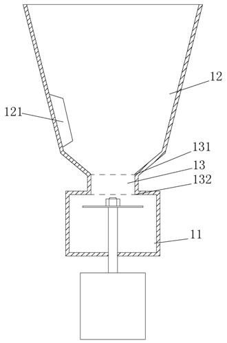
[0045] Such as image 3 Shown is a schematic structural diagram of the second embodiment of the present invention. The difference from Embodiment 1 is that the food processing machine in this embodiment has a structure with a motor under it, and the flow-gathering port 13 is tubular, and the flow-gathering port 13 has a water inlet 131 and a water outlet 132. The water inlet 131 is located in the mixing chamber 12 , and the water outlet 132 is located in the crushing chamber 11 .

[0046] In addition, in this embodiment, the converging port is set as a tubular structure, the slurry enters from the water inlet and flows out from the water outlet, and the material has the effect of gravity acceleration in the process of passing through the converging port, and the accelerated material and the slurry After hitting the crushing blade, the crushing efficiency of the material can be improved to a greater extent. At the same time, setting the converging port into a tubular structur...

Embodiment 3

[0053] Such as Figure 4 , Figure 5 Shown is a schematic structural view of the third embodiment of the present invention. The difference from Embodiment 2 is that in this embodiment, the bottom of the mixing chamber 12 has a converging portion 14 protruding toward the center of the container, and the top surface of the converging portion 14 is inclined downward relative to the horizontal plane. 14 The inclination angle α relative to the horizontal plane is generally less than 80°. Since the converging part 14 is in the shape of an inverted cone, the materials and slurry in the mixing chamber can be collected, making it easier for the materials to flow in from the converging port. At the same time, the top of the crushing chamber 11 is provided with a shielding part 15 that limits the material in the crushing chamber 11 (the shielding part 15 can further prevent the material from being ejected from the crushing chamber 11 after being collided by the crushing blade), wherein...


PUM


Abstract

The invention relates to a small kitchen appliance, in particular to a food processing machine. The crushing device for the food processing machine includes a container, which is characterized in that: the container includes a crushing chamber located at the bottom of the container, a mixing chamber arranged above the crushing chamber and It is used to connect the crushing chamber and the converging port of the mixing chamber. The crushing chamber is provided with a crushing blade, and the crushing blade has a pressing part that drives the slurry to move toward the bottom of the crushing chamber. The capacity of the crushing chamber is 22mL~ 380mL. The material of the present invention will be concentrated in the crushing chamber in a small space, and the crushing chamber is provided with crushing blades, therefore, most of the materials will be concentrated in the crushing chamber for crushing. Compared with the prior art, the structure is simple and the cost is low. It is relatively low, and the crushing device can crush the materials intensively, the crushing efficiency is high, there will be no bean lumps, and it is easy to clean.

Description

technical field [0001] The invention relates to small kitchen appliances, in particular to a food processing machine. Background technique [0002] The existing soymilk machine includes a machine head and a cup body. The machine head is located in the cup body, and the cup body is generally in the shape of a straight barrel, and the diameter of the cup body is much larger than the rotation diameter of the crushing blade. Therefore, During the pulping process, the crushing blade drives the material to rotate at a high speed, and the material will move away from the crushing blade under the action of centrifugal force, which causes the phenomenon that the material cannot be crushed intensively by the crushing blade. Even when the material hits the cup wall at high speed by the centrifugal force, it will rebound towards the crushing blade. However, because the distance between the cup wall and the crushing blade is relatively long, the energy of the material particles will be w...

Claims


Application Information

Patent Timeline
Patent Type & Authority Patents(China)
IPC IPC(8): A47J43/044A47J43/07
CPCA47J43/044A47J43/0711A47J43/0727
Inventor 王旭宁王毓吉王军伟王国华苏锋
Owner JOYOUNG CO LTD
Learn More