
Vehicle lamp bead and vehicle lamp refitting method

A lamp bead and vehicle technology, which is applied in the field of vehicle lighting, can solve the problems of large power consumption of halogen lamps, increase user costs, inability to achieve lighting effects, etc., and achieve good energy-saving effects.

Inactive Publication Date: 2018-07-20
顾鹤彬
View PDF0 Cites 0 Cited by
  • Summary
  • Abstract
  • Description
  • Claims
  • Application Information

AI Technical Summary

Problems solved by technology

[0002] With the rapid development of the automobile industry, not only the technical performance of the vehicle is continuously improved, but also the shape of the body is constantly updated to meet the needs of different consumers. The car light is no longer simply used as lighting, but as a decorative part , and its shapes are various, which brings a problem - poor versatility, once the car light is broken, you must buy the original car light to achieve the best effect, which will increase the user cost
[0003] In addition, the lamp beads used for traditional automotive lighting usually use halogen lamp beads, which consume a lot of power
LED light source has the characteristics of energy saving and high efficiency. However, due to the shape of different vehicle lights, the shapes and sizes of lamp beads and reflector cups, if LED light sources are used to replace the lamp beads of car lights, it cannot be universally matched to all vehicles, and LED light sources are different from traditional ones. The luminous angle of the halogen bulb is very different. If it is directly replaced, it will not cooperate well with the reflector in the original lamp head of the vehicle, and the best lighting effect cannot be achieved.

Method used


Image

  • Vehicle lamp bead and vehicle lamp refitting method
  • Vehicle lamp bead and vehicle lamp refitting method

Examples


Embodiment Construction

[0018] The present invention will be further described below with reference to the accompanying drawings and embodiments.

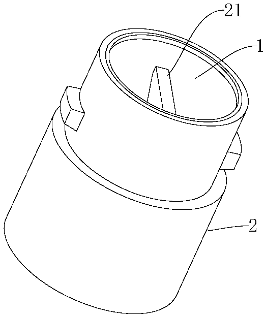
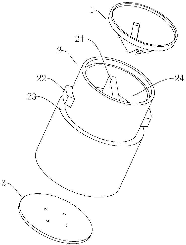
[0019] Please refer to figure 1 and figure 2 , The lamp beads for this vehicle include a light source body, the light source body is two sets of LED light sources (not shown in the figure), the lamp beads for vehicles also include a cylindrical metal body 2, the inner front end of the metal body 2 The light source cavity 24, the rear end (the lower side of the light source cavity 24 in the figure) is the power supply cavity, the light source cavity 24 is provided with a reflector 1 and a partition 21, and the partition 21 connects the reflector along the axis of the reflector 1. The space in 1 is divided into half, the two groups of LED light sources are supported in the reflector 1 and are located on both sides of the partition plate 21 respectively, and a circuit board (not shown in the figure) is installed in the power supply cavity, so the The circ...


PUM


Abstract

The invention relates to a vehicle lamp bead and a vehicle lamp refitting method. The lamp bead comprises a light source body and a barrel-shaped metal body, the light source body is composed of two LED light sources, a light source cavity is arranged at the front end of the interior of the metal body, a power source cavity is arranged at the back end of the interior of the metal body, a light reflection cup and a separating plate are arranged in the light source cavity, space in the light reflection cup is divided into two halves through the separating plate along the axis of the light reflection cup, the two LED light sources are supported to the two sides of the separating plate and in the light reflection cup, a circuit board in the power source cavity is connected with the two LED light sources, and a connecting device is arranged on the periphery of the metal body. The refitting method comprises the steps that an original lamp bead of a vehicle is disassembled, the above vehiclelamp bead is installed on a lamp bead connector of the vehicle, and the separating plate is in the horizontal state. The lamp bead integrates the light reflection cup, the LED light sources and a radiating device, the universality is good, and the best lighting effect can be achieved when the lamp bead is installed on various vehicles. According to the vehicle lamp bead, the LED light sources areadopted, and the energy saving effect is good. Two lighting effects of distance light and near light can be achieved.

Description

technical field [0001] The invention relates to the field of vehicle lighting, in particular to a lamp bead for vehicles and a method for refitting the lamp. Background technique [0002] With the rapid development of the automobile industry, not only the technical performance of the vehicle is continuously improved, but also the body shape is constantly updated to meet the needs of different consumers. The lamp is no longer simply used for lighting, but also as a decorative part. , its shapes are various, which brings a problem - poor versatility, once the lamp is broken, you must buy the original lamp to achieve the best effect, which will increase the user cost. [0003] In addition, the lamp beads used for traditional automotive lighting usually use halogen lamp beads, which consume a lot of power. LED light sources have the characteristics of energy saving and high efficiency, but due to the different shapes of vehicle lights, the shapes and sizes of lamp beads and ref...

Claims


Application Information

Patent Timeline
Patent Type & Authority Applications(China)
IPC IPC(8): F21S41/141F21V7/04F21V19/00F21V23/00F21V17/10H05B33/08F21V29/89F21Y115/10F21W107/10H05B44/00
CPCF21V7/041F21V17/10F21V19/001F21V23/004F21V29/89F21Y2115/10H05B45/00
Inventor 顾鹤彬
Owner 顾鹤彬
Learn More