Candan universal joint synchronization oil injection equipment and method thereof

A cross universal joint and grease technology, which is applied in the direction of mechanical equipment, elastic couplings, engine components, etc., can solve the problems of reducing the efficiency of oil injection, insufficient oil, and inability to synchronize one-time oil injection, etc., to improve oil injection efficiency, The effect of improving product quality

Pending Publication Date: 2018-07-20
ZHEJIANG QIDIE AUTOMOBILE PARTS CO LTD
View PDF1 Cites 2 Cited by
  • Summary
  • Abstract
  • Description
  • Claims
  • Application Information

AI Technical Summary

Problems solved by technology

[0004] However, in the actual use process, the inventor found that it has the following technical problems: first, it still cannot realize synchronous one-time oil injection to the four holes of the universal joint, and the oil injection efficiency; secondly, it adopts a weighing device to weigh The way of taking quantitative grease to achieve the quantitative amount of each oil injection, the structure is more complicated and further reduces the efficiency of its oil injection; moreover, if it uses the method of extending the oil injection head into the oil injection hole for oil injection, the injection will often be removed when it is abdicated. Part of the good oil is brought out, resulting in insufficient oil in the hole

Method used


Image

  • Candan universal joint synchronization oil injection equipment and method thereof
  • Candan universal joint synchronization oil injection equipment and method thereof
  • Candan universal joint synchronization oil injection equipment and method thereof

Examples


Embodiment 1

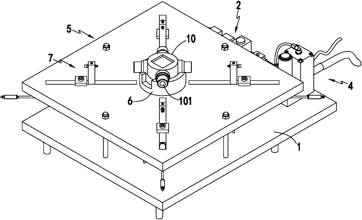
[0050] Such as figure 1 , figure 2 , Figure 5 , Image 6 with Figure 7 As shown, the synchronous grease injection equipment for cross universal joints includes a base 1, an electric control device 2 installed on the base 1, an air intake control device 3 and an oil supply device 4, and a guide support unit 5 is also arranged above the base 1. , the guide support unit 5 is provided with a positioning jig 6 for positioning the cross joint 10 to be greased, and the positioning jig 6 is provided with the same position as the oil injection hole 101 of the cross joint 10 along the circumferential path. A corresponding oil injection device 7;

[0051] A plurality of oil injection devices 7 corresponding to the positions of the oil injection holes 101 move synchronously along the radial direction of the oil injection holes 101 corresponding to the positions of the oil injection devices 7 towards the center position of the Oldham joint 10 under the control of the air intake cont...

Embodiment 2

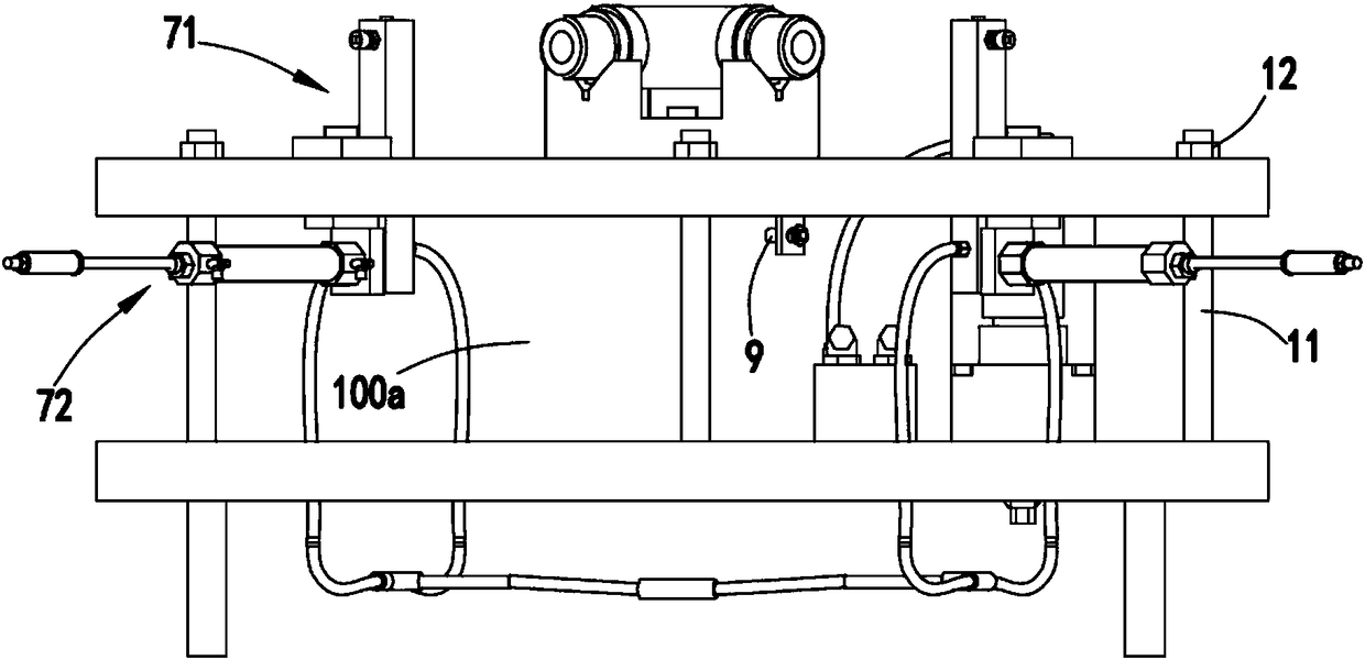
[0072] Such as image 3 with Image 6 , wherein the same or corresponding components as those in Embodiment 1 use the corresponding reference numerals as in Embodiment 1. For the sake of simplicity, only the differences from Embodiment 1 will be described below. The difference between the second embodiment and the first embodiment is that: as a preference, the oil injection is performed between the oil injection mechanism 71 and the oil injection hole 101 of the Oldham joint 10 using an eccentric non-contact oil injection method.

[0073] Such as image 3 As shown, further, the oil injection nozzle 711 of the oil injection mechanism 71 communicates with the oil supply device 4 through the oil passage. there is a gap between

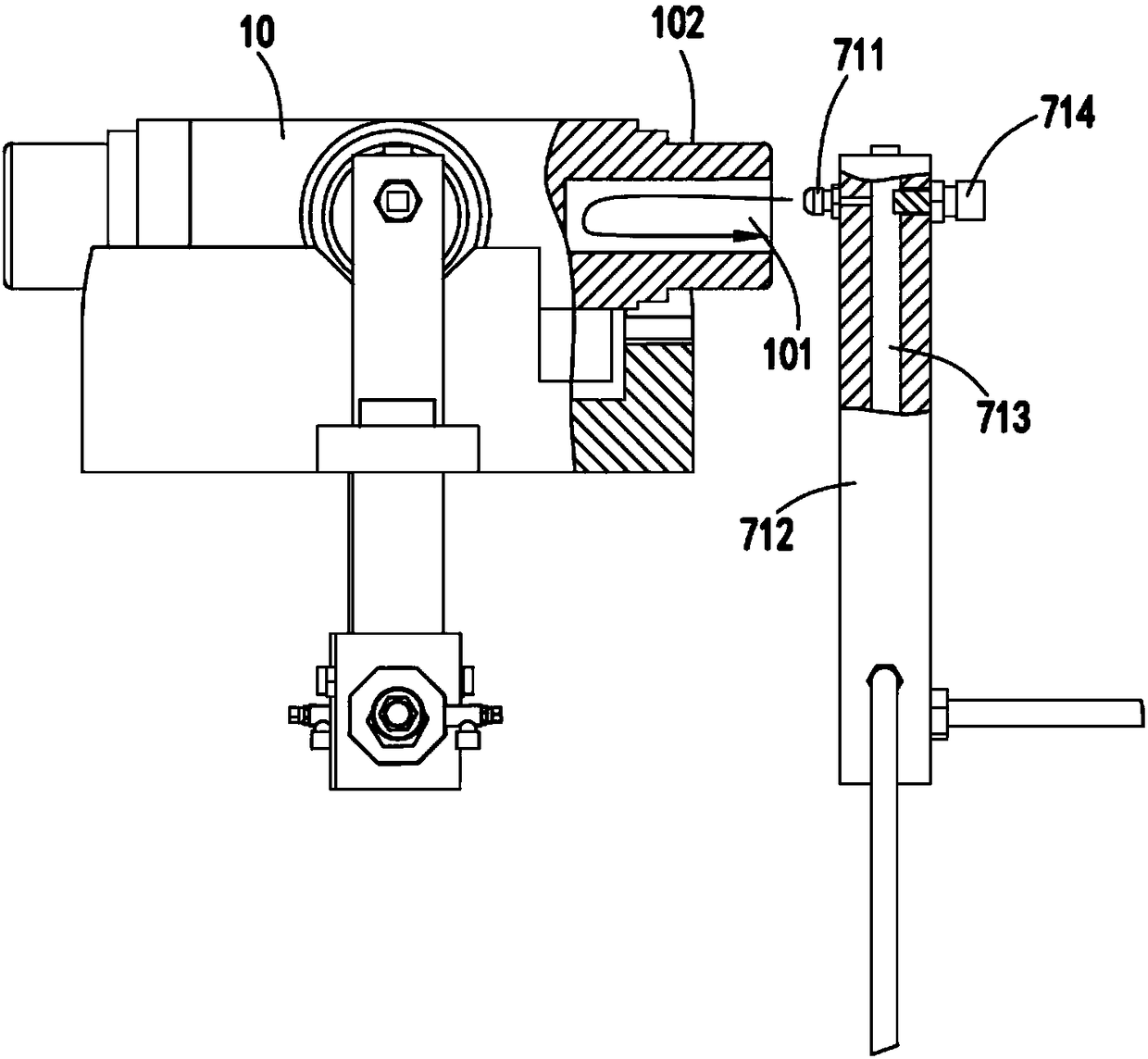
[0074] Specifically, the oil injection mechanism 71 includes a sliding block 712 that slides along the guide groove 511 driven by the propulsion mechanism 72, the oil injection nozzle 711 is arranged on the upper end of the sliding block 712, and the i...

Embodiment 3

[0082] Such as figure 2 , wherein the same or corresponding components as those in Embodiment 2 use the corresponding reference numerals as in Embodiment 2. For the sake of simplicity, only the differences from Embodiment 2 are described below. The difference between the third embodiment and the second embodiment is: further, the vertical distance between the oil injection nozzle 711 and the support plate 51 is d2, and d2 satisfies 27cm≤d2≤30cm.

[0083] In this embodiment, the oil nozzle 711 on the sliding block 712 is set within a certain height range according to the actual production situation, so that when dealing with the oil injection processing of products of different specifications, the operator only needs to replace the fixture body 61 of different specifications and sizes. , there is no need to adjust the height of the oil injection nozzle 711 on the oil injection device 7, which greatly improves the versatility and convenience of the equipment.


PUM


Abstract

The invention relates to candan universal joint synchronization oil injection equipment and a method thereof. The candan universal joint synchronization oil injection equipment comprises a base, an electric control device installed on the base, an air inlet control device and an oil feeding device, a guide supporting unit is arranged above the base and is provided with a positioning clamp for positioning a candan universal joint, and oil injection devices corresponding to the oil injection hole in a one-to-one manner are arranged on the periphery of the positioning clamp along the circumferential route; the multiple oil injection devices are controlled by the air inlet control device to synchronously move towards the center position of the candan universal joint in the radial directions ofthe oil injection holes corresponding to the oil injection devices in position, oil is injected from the oil injection devices to the oil injection holes through control of an oil supply device afterthe oil injection devices are moved to the specific positions, and the oil inlet control device controls the oil injection devices to reset after oil injection is finished. The candan universal jointsynchronization oil injection equipment and the method solve the problems that multiple holes need to be subject to oil injection one by one in the candan universal joint oil injection process, the oil injection efficiency is low, oil amount in all holes is difficult to balance, oil injection into blind holes are prone to being brought out after oil injection resetting is carried out, the oil amount in the blind hole is insufficient, and consequently the product using effect is influenced.

Description

technical field [0001] The invention relates to the technical field of grease injection equipment for universal joints, in particular to synchronous grease injection equipment for cross universal joints and a method thereof. Background technique [0002] The universal transmission device used in the automobile transmission system is generally composed of a universal joint and a transmission shaft. The universal joint realizes shaft power output in different directions. It is also a very important part of the car. The holes of some universal joints are Through holes, it only needs to inject grease from one oil injection port and then spread to other parts, while some are blind holes, each hole needs to be greased separately, for example, cross universal joints need four blind holes. The holes are respectively greased. In the prior art, the operator generally greases the four holes one by one. The production efficiency is low and it is difficult to ensure that the oil quantity...

Claims


Application Information

Patent Timeline
Patent Type & Authority Applications(China)
IPC IPC(8): F16N7/14F16N21/00F16D3/26
CPCF16N7/14F16D3/26F16N21/00
Inventor 闻吾其许建立华林
Owner ZHEJIANG QIDIE AUTOMOBILE PARTS CO LTD
Why Eureka
Try Eureka