
Novel hub

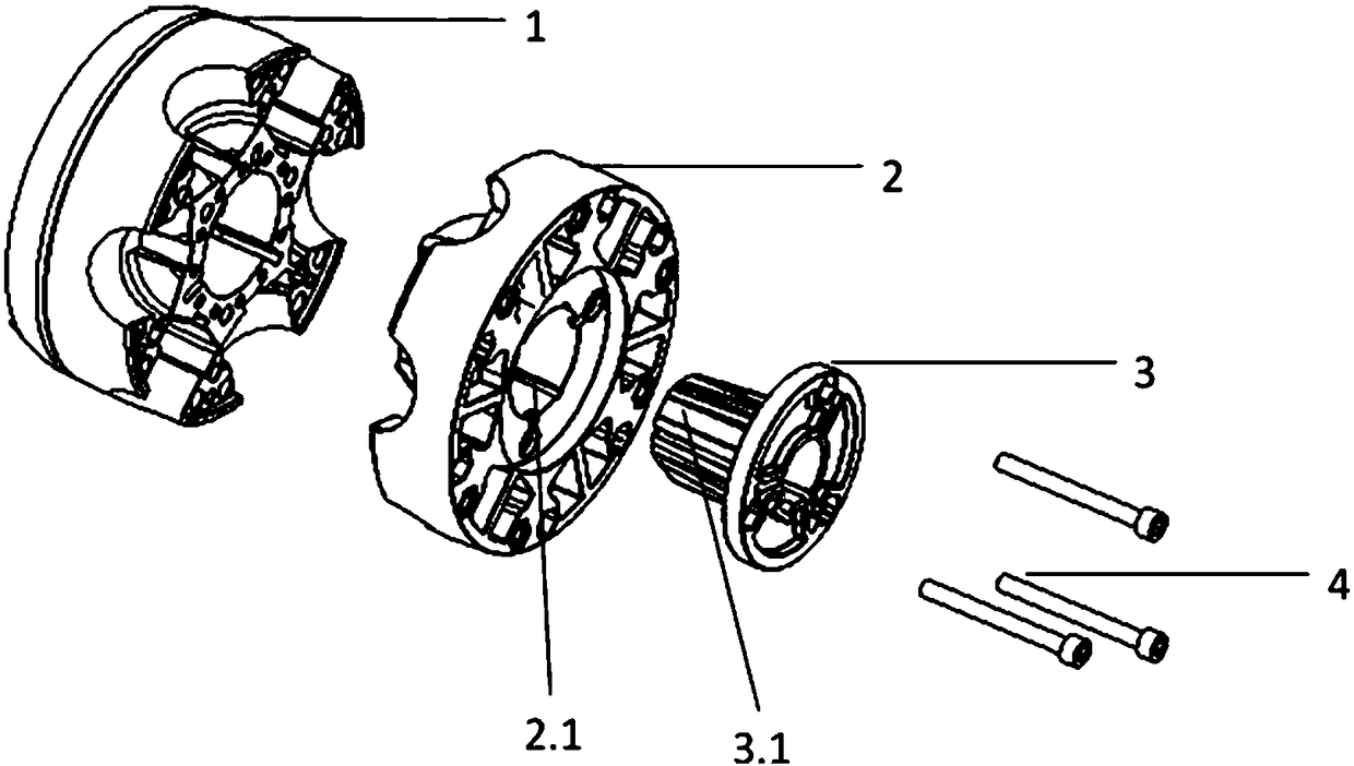
A new type of wheel hub technology, applied in the mechanical field, can solve the problems of enlarged size, large riser, long manufacturing cycle, etc., and achieve the effect of reducing the wind resistance area, increasing the fan efficiency, and having a consistent installation angle.

Pending Publication Date: 2018-07-20
上海优睿农牧科技有限公司
View PDF2 Cites 0 Cited by
  • Summary
  • Abstract
  • Description
  • Claims
  • Application Information

AI Technical Summary

Problems solved by technology

However, at present, many fan equipment manufacturers at home and abroad have some problems in the casting process design of the wheel hub. For example, some companies use large gates, large risers, large processing volume, high temperature filling, etc., resulting in the casting process yield rate. Not high, few companies can achieve more than 60%, and due to the increased size of the wheel hub, the machining cycle after casting is prolonged, and due to the increased size, the pouring temperature is high, the energy consumption is large, and it is easy to cause Graphitization drift occurs during the solidification process of the hub, which seriously affects its performance
These have resulted in high production costs, long manufacturing cycles, low process yields, and unstable performance of fan hubs.
[0006] To sum up, the fan hubs of the prior art have the following disadvantages: 1. The installation angle adjustment accuracy of the fan blades is not high, and the setting of the adjustment angle is complicated and error-prone; 2. The manufacturing process of the hubs of the prior art has low yield and low cost high

Method used


Image

  • Novel hub
  • Novel hub
  • Novel hub

Examples


Embodiment Construction

[0035] The idea, specific structure and technical effects of the present invention will be further described below in conjunction with the accompanying drawings, so as to fully understand the purpose, features and effects of the present invention.

[0036] The wedge fit in the present invention refers to the close fit of two matching wedges.

[0037] Injection molding according to the present invention refers to a model with a certain shape, which is formed by injecting the colloid in the molten state into the mold cavity through pressure. The process principle is: melting the solid plastic according to a certain melting point, and using the pressure of the injection machine to A certain speed is injected into the mold, and the mold is cooled by water channels to solidify the plastic to obtain the same product as the designed cavity. It is mainly used for the molding of thermoplastics, and can also be used for the molding of thermosetting plastics.

[0038] Schematic diagram ...


PUM


Abstract

The invention discloses a novel hub. The novel hub is connected with a transmission shaft and fan blades. The novel hub comprises a front hub, a rear hub and angle adjustment blocks. The inner surfaceof the front hub and the inner surface of the rear hub are each provided with multiple fan blade assembling grooves in an equally-spaced manner. The angle adjustment blocks are arranged in the fan blade assembling grooves and matched with the fan blades and the fan blade assembling grooves through wedges. By means of the fan blade hub, the blade mounting angle can be adjusted in a high-precision,convenient and fast manner, and the fan blade hub can be mounted and dismounted rapidly.

Description

technical field [0001] The invention relates to the field of machinery, in particular to a new wheel hub. Background technique [0002] The fan hub is a key component in the fan, and its performance is a major factor that determines the performance, energy consumption and efficiency of the fan. [0003] The Chinese patent adjustable impeller hub with the patent number CN206111658U discloses an adjustable impeller hub. The adjustable impeller hub is formed by merging two symmetrically distributed half-hub bodies. The half-hub body has a circular structure and half The inner surface of the hub body is distributed with a number of fan blade assembly grooves, and the fan blade assembly grooves are distributed in a ring shape and equidistant along the edge of the half hub body. There are a number of bolt holes on the half hub body, and the two symmetrically distributed half The hub bodies are fixed by bolts, and each bolt hole is equipped with a bolt, and the center of half of t...

Claims


Application Information

Patent Timeline
IPC IPC(8): F04D29/26F04D29/60
CPCF04D29/26F04D29/601
Inventor 王松旗
Owner 上海优睿农牧科技有限公司
Learn More