
Tubing shifting conveying device and using method thereof

An oil pipe and mounting seat technology, which is applied to drilling pipes, casings, and earth-moving drilling and mining, etc., can solve the problems of not being able to be thrown to the top automatically, there are potential safety hazards, and manual handling is required. The effect of eliminating safety hazards and compact structure

Pending Publication Date: 2018-07-20
BC P INC CHINA NAT PETROLEUM CORP +1
View PDF0 Cites 0 Cited by
  • Summary
  • Abstract
  • Description
  • Claims
  • Application Information

AI Technical Summary

Problems solved by technology

[0003] The present invention provides a oil pipe transfer device and its use method, which overcomes the deficiencies of the above-mentioned prior art, and can effectively solve the cumbersome operation existing in the operation of the existing transfer hook, the transfer efficiency is low, and there are potential safety hazards. When drilling the pipe, it cannot be thrown to the top automatically, and manual handling is required, which is a problem with large limitations.

Method used


Image

  • Tubing shifting conveying device and using method thereof
  • Tubing shifting conveying device and using method thereof
  • Tubing shifting conveying device and using method thereof

Examples


Embodiment 1

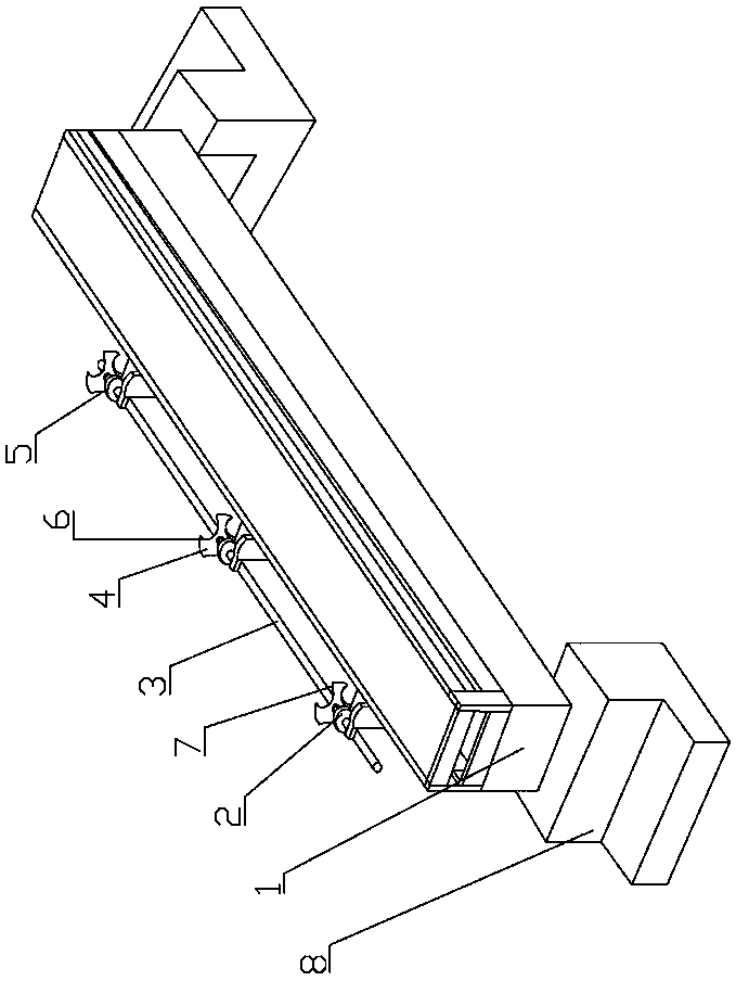
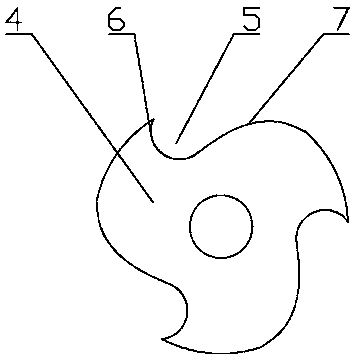
[0022] Embodiment one: as attached figure 1 , 2 , 3, the oil pipe dialing device includes a mounting seat 1, a bearing seat 2, a transmission shaft 3, a bearing body, a dial wheel 4 and a power drive device, and at least two bearing seats 2 are fixed on the mounting seat 1 at intervals along the front and rear , the transmission shaft 3 passes through the middle of the corresponding bearing housing 2 from front to back in sequence, and the front end of the transmission shaft 3 is located in front of the front bearing housing 2, the rear end of the transmission shaft 3 is located behind the rear bearing housing 2, and the transmission shaft 3 and the bearing seat 2 are installed with a bearing body; the outer side of the transmission shaft 3 is fixed with at least two dials 4 along the front and rear directions, and each dial 4 is evenly distributed along the circumference with at least one that can make the oil pipe be stuck from one side. Insert and flip the bayonet 5 that s...

Embodiment 2

[0029] Embodiment two: as attached figure 1 , 2 , 3, the method for using the tubing transfer device includes the following steps:

[0030] The first step is to place the tubing transfer device at the wellhead, make the left side of the tubing transfer device close to the existing tubing retention place, and make the left side of the tubing transfer device close to the existing tubing delivery place;

[0031]The second step is to transfer the tubing from the outlet of the tubing to the place where the tubing stays. In the initial state, a set of front and rear corresponding bayonets 5 are directed towards the outlet of the tubing, and the heights of the two match. When the dial wheel 4 rotates counterclockwise, the sending position should match the height of the place where the oil pipe is temporarily left. First, send the oil pipe on the place where the oil pipe is sent out to the corresponding bayonet 5, and then drive the power drive device 5 to drive the transmission shaf...


PUM


Abstract

The invention relates to the technical field of petroleum engineering equipment, and provides a tubing shifting conveying device and a using method thereof. The tubing shifting conveying device comprises a mounting seat, bearing seats, a transmission shaft, a bearing body, shifting wheels and a power driving device, wherein the at least two bearing seats are fixed to the mounting seat in the front-rear direction at intervals, and the transmission shaft sequentially penetrates through the middle of the corresponding bearing seat from front to rear; the front end of the transmission shaft is located in front of the bearing seat on the front side, the rear end of the transmission shaft is located behind the bearing seat on the rear side, and the bearing body is mounted between the transmission shaft and the bearing seats; and the at least two shifting wheels are fixed to the outer side of the transmission shaft in the front-rear direction at intervals. The using method of the tubing shifting conveying device comprises the step that 1, the tubing shifting conveying device is placed at a wellhead to make the left side of the tubing shifting conveying device be close to an existing tubing temporary storing place. According to the tubing shifting conveying device and the using method thereof, automatic shifting conveying operation of an tubing can be achieved through change of a clamping opening from one position to another position; and whole shifting conveying operation is easy and convenient, both time and labor are saved, continuous shifting conveying operation can be achieved, the shifting conveying efficiency is high, and manual carrying is not required.

Description

technical field [0001] The invention relates to the technical field of petroleum engineering equipment, and relates to an oil pipe transfer device and a use method thereof. Background technique [0002] In the conventional workover operations of oil and water wells, it is basically all to be pulled and carried by manpower. In the operation of lowering the tubing, usually the workover three-post personnel manually roll the tubing from the rear end of the tubing bridge to the side of the tubing slideway, and then the three-post personnel lift it onto the tubing block on the tubing slideway and push it to the wellhead for convenience. The wellhead worker buckles the elevator. The average weight of a φ73mm tubing is 90kg, and the depth of a well is 2000m. The lifting and lowering operation of a pipe string is equivalent to handling a weight of 30-40 tons. The labor intensity of the workers is high, and the safety factor is low, requiring a degree of cooperation among personnel....

Claims


Application Information

Patent Timeline
Patent Type & Authority Applications(China)
IPC IPC(8): E21B19/14
CPCE21B19/146
Inventor 李江生王宁刘剑赵权栗建伟黄磊江美淋李焕敏阿米娜·麦麦提
Owner BC P INC CHINA NAT PETROLEUM CORP
Learn More