Variable power optical system, optical device, and method for producing variable power optical system
A technology of optical system and manufacturing method, applied in the field of variable power optical system, capable of solving problems such as insufficient optical performance
- Summary
- Abstract
- Description
- Claims
- Application Information
AI Technical Summary
Problems solved by technology
Method used
Image
Examples
Embodiment
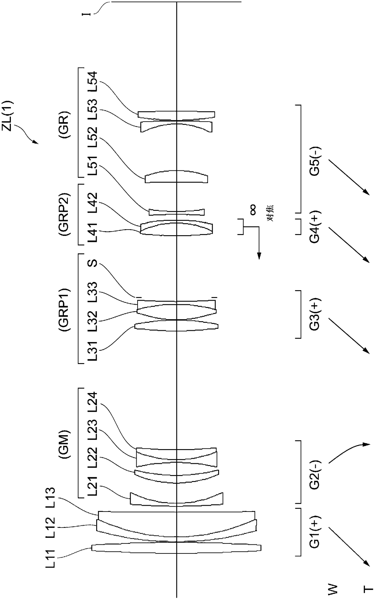
[0105] Hereinafter, a variable power optical system (zoom lens) ZL according to an example of the present embodiment will be described with reference to the drawings. figure 1 , Figure 6 , Figure 11 , Figure 16 , Figure 21 , Figure 26 It is a cross-sectional view showing the structure and power distribution of the variable power optical system ZL{ZL(1)-ZL(6)} of the first to sixth embodiments. In the lower part of the cross-sectional views of the variable power optical systems ZL(1) to ZL(6), arrows show the trailing light of each lens group when zooming from the wide-angle end state (W) to the telephoto end state (T). The direction of movement of the axis. Furthermore, the moving direction of the follow-up side lens group GRP2 as the focusing lens group when focusing from infinity to a close-distance object is indicated by an arrow together with the word "focus".
[0106] In these figure 1 , Figure 6 , Figure 11 , Figure 16 , Figure 21 , Figure 26 In , e...
no. 1 Embodiment
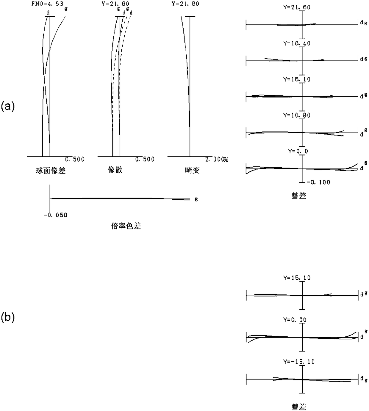
[0116] use Figure 1 to Figure 5 And Table 1 describes the first embodiment. figure 1 It is a figure which shows the lens structure of the variable power optical system of the 1st Example of this embodiment. The variable power optical system ZL(1) of the first embodiment consists of the first lens group G1 with positive refractive power, the second lens group G2 with negative refractive power, and the second lens group G2 with positive optical power arranged in order from the object side. The power third lens group G3, the aperture stop S, the fourth lens group G4 having positive power, and the fifth lens group G5 having negative power constitute. When zooming from the wide-angle end state (W) to the telephoto end state (T), the first to fifth lens groups G1 to G5 respectively figure 1Move in the direction indicated by the arrow. In this embodiment, the second lens group G2 constitutes the middle group GM, the third lens group G3 and the aperture stop S constitute the middl...
no. 2 Embodiment
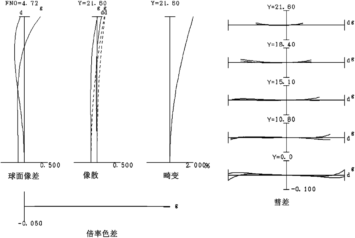
[0146] use Figure 6 ~ Figure 10 And Table 2 describes the second embodiment. Figure 6 It is a figure which shows the lens structure of the variable power optical system of the 2nd Example of this embodiment. The variable power optical system ZL(2) of the second embodiment consists of the first lens group G1 with positive refractive power, the second lens group G2 with negative refractive power, and the second lens group G2 with positive optical power arranged in order from the object side. The power third lens group G3, the aperture stop S, the fourth lens group G4 having positive power, and the fifth lens group G5 having negative power constitute. When zooming from the wide-angle end state (W) to the telephoto end state (T), the first to fifth lens groups G1 to G5 respectively Figure 6 Move in the direction indicated by the arrow. In this embodiment, the second lens group G2 constitutes the middle group GM, the third lens group G3 and the aperture stop S constitute the ...
PUM
 Abstract
Description
Claims
Application Information
 - R&D Engineer
- R&D Manager
- IP Professional
- Industry Leading Data Capabilities
- Powerful AI technology
- Patent DNA Extraction
Browse by: Latest US Patents, China's latest patents, Technical Efficacy Thesaurus, Application Domain, Technology Topic, Popular Technical Reports.
© 2024 PatSnap. All rights reserved.Legal|Privacy policy|Modern Slavery Act Transparency Statement|Sitemap|About US| Contact US: help@patsnap.com


