Eureka AIR delivers breakthrough ideas for toughest innovation challenges, trusted by R&D personnel around the world.

Dynamically-changeable abdominal simulator system

a simulator and dynamic technology, applied in the field of biomedical simulation devices, can solve the problems of appendicitis, ectopic, inability to replicate other abdominal disorders, etc., and achieve the effect of accurately diagnosing a wide range of abdominal ailments

Inactive Publication Date: 2015-07-21
SMARTUMMY
View PDF7 Cites 44 Cited by
  • Summary
  • Abstract
  • Description
  • Claims
  • Application Information

AI Technical Summary

Benefits of technology

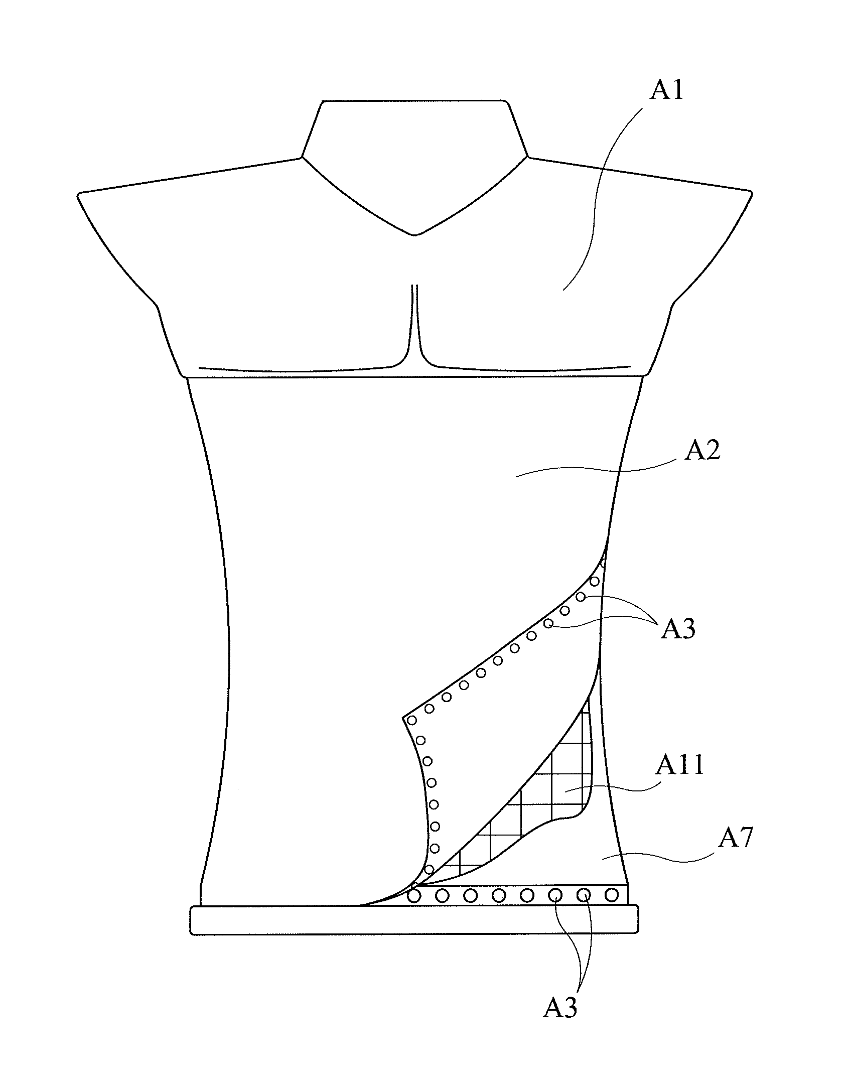
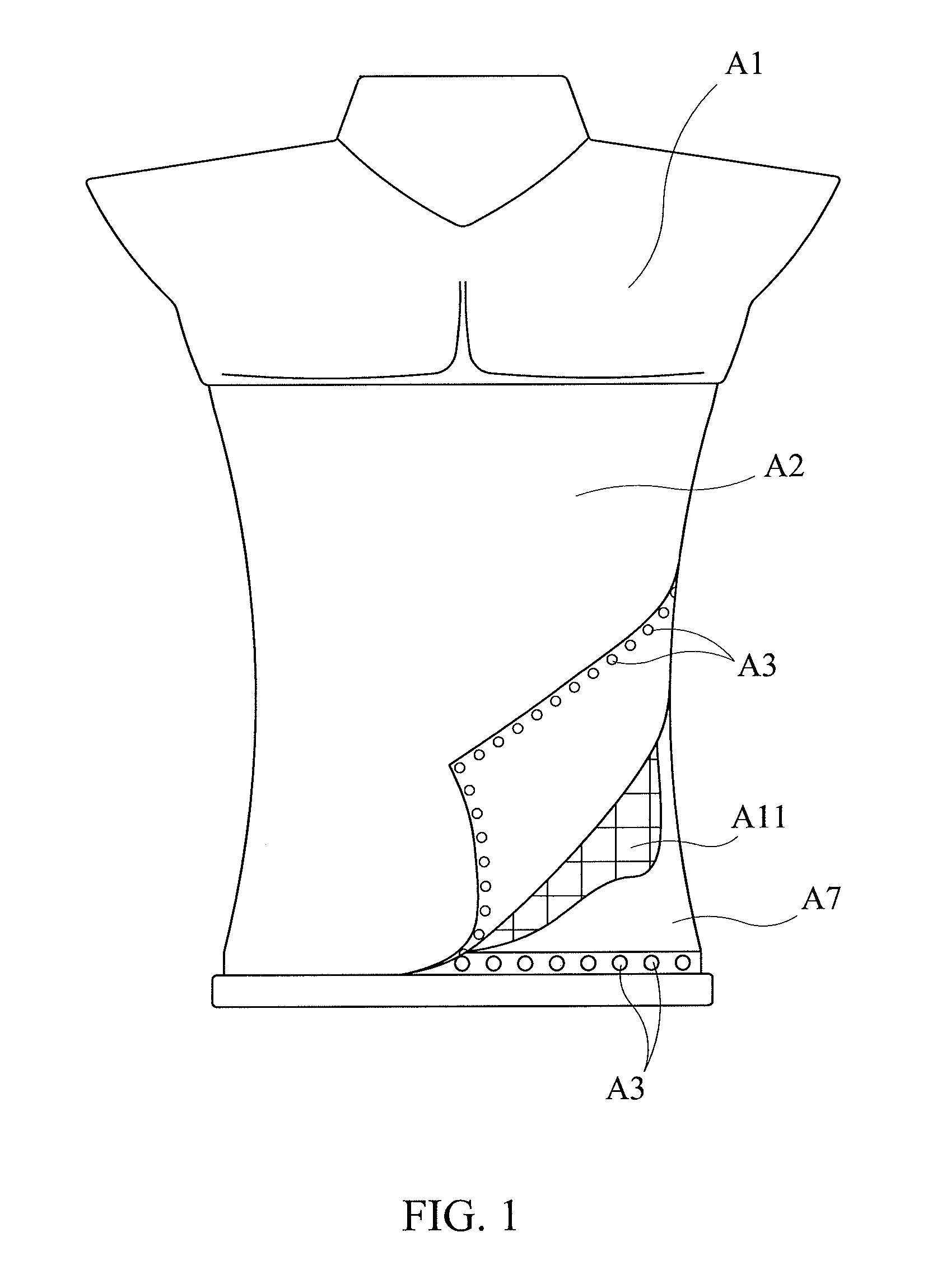
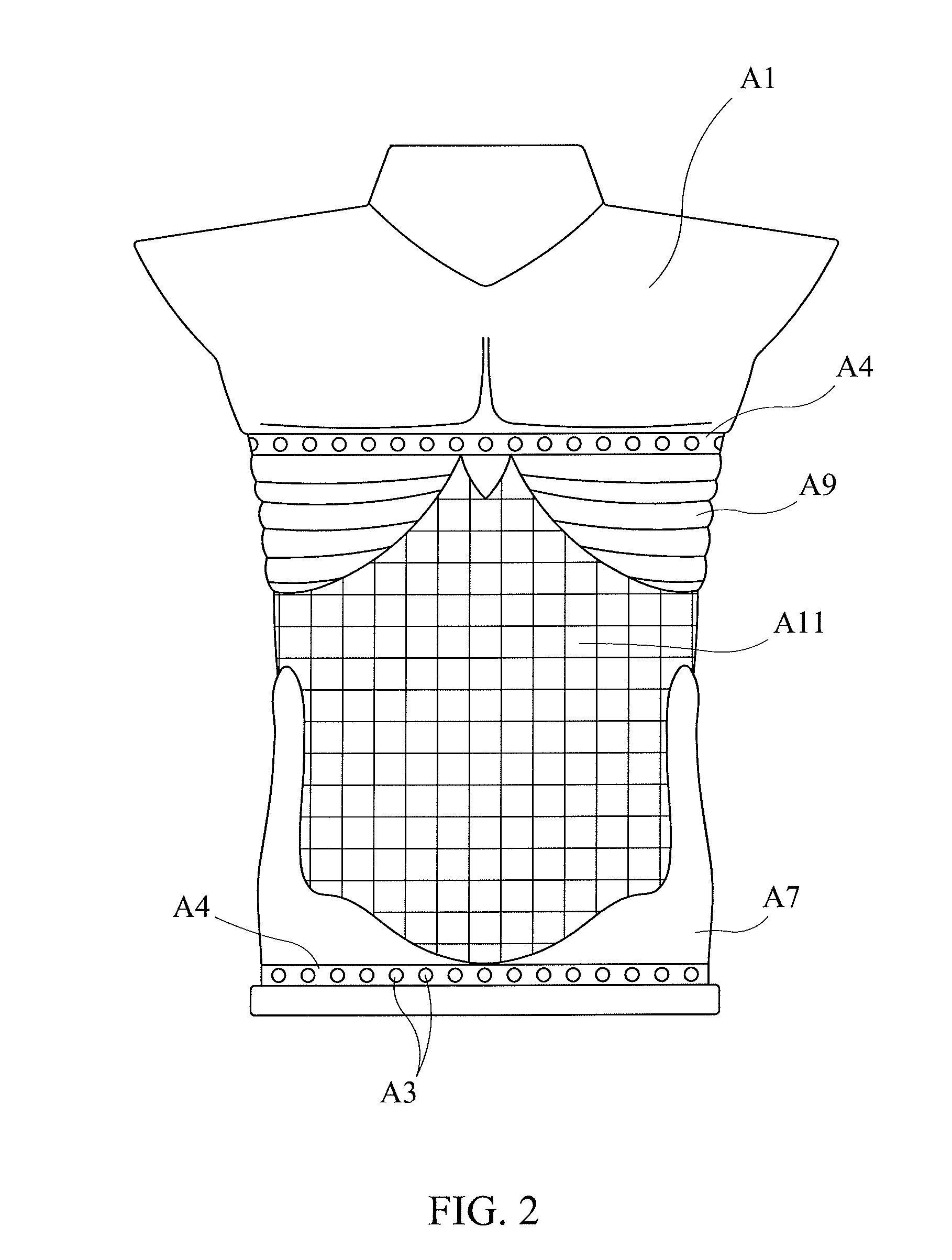
[0005]In accordance with the present invention, a dynamically-changeable abdominal simulator system comprises a patient manikin having an abdominal cavity covered by a sheet of synthetic skin, which contains an array of inflatable elements covering distinct areas of pressurization over the length and width of the abdominal cavity. The inflatable elements are separately and independently supplied with a pressurized medium so that they can be dynamically configured to simulate a wide range of abdominal ailments and / or conditional expressions thereof, thereby providing an effective simulator training tool for practicing abdominal palpation exams. The inflation system for pressurization of the array of inflatable elements employs an electronic control module with an on-board microprocessor. The electronic control module communicates with an external computer that provides a graphical user interface for the user to run software-programmed simulation routines in conjunction with the operation of the manikin.
[0006]In a preferred embodiment, the array of inflatable elements is arranged as a grid of inflatable cells in a plurality of x rows and y columns defining distinct unit areas of pressurization. An inflation manifold employs x-y electronically controlled valves controlled by the electronic control module to inject pressurized medium into or discharge it from the inflatable cells. The electronic control module is embedded in the manikin with the inflation manifold for portability, and communicates with an external computer, laptop, or mobile device that provides a graphical user interface (GUI) for the user to run software-programmed simulation routines. The GUI interface is designed to allow a user to readily select from a wide range of abdominal ailments and to operate the inflation system under software control. This enables the array of inflatable elements to be dynamically configured in the manikin's abdominal cavity to mimic any selected ailment and / or conditional expressions thereof. For example, an abdominal ailment such as hepatomegaly (enlarged liver) can be simulated by inflating several cells in the liver's position of the grid-array with varying pressures to replicate the outline shape and feel of a hepatomegaly condition.
[0007]In a particularly preferred embodiment, the synthetic skin covers the manikin torso from the chest down to the pubis. Underneath the skin layer are several synthetic bone structures that will emulate the ribcage and iliac crests and are fused to the manikin torso. Additionally, the abdominal cavity contains a grid of inflatables made of rigid material to retain their shape and spanning the entire abdominal cavity. The inflatables are fixated in position at the top and bottom faces. Attached to the bottom of the abdominal cavity is an inflatable grid support structure that mimics the contour of the abdominal cavity. Tubing for each inflatable runs through the grid-like support structure and attaches to each inflatable. The top of each inflatable is fused to a single membrane of low elastic modulous material that spans the abdominal cavity region. This membrane is attached to the underside of the manikin walls to keep the inflatables fixated in place. Inflation is accomplished using a manifold system capable of both hydraulic and pneumatic fluid flow connected to the inflatables via tubing. The manifold is engineered using moveable piston shafts and either hydraulic or pneumatic valves aligned in a row / column format where each piston shaft is individually controlled using an electronic actuator that is either a liner actuator, push / pull solenoid, air valve, or the like. The hydraulic or pneumatic valves are also electronic and individually controlled. Each piston shaft is aligned with a valve in a row / column orientation. When fluid flow is supplied from a valve and a piston is energized in one direction, a pressure differential induces inflation of each balloon attached to a port on the manifold that is opened. The flow of pressurized medium into and out of the manifold is accomplished using separate supply and exhaust channels in the manifold. These channels are separated using ring gaskets fitted onto the piston shaft. Movement of the piston allows for opening and closing of the fill and exhaust channels.
[0010]The abdominal simulator system of the present invention enables realistic and dynamically changeable abdominal conditions to be simulated for training medical, nursing, and paramedic students to palpate and accurately diagnose a wide range of abdominal ailments and / or conditional expressions thereof. The associated user control interface enables an operator to dynamically simulate a comprehensive training environment, including changing conditions, associated sounds, medical images, and training videos for a wide range of abdominal ailments (e.g., appendicitis, hernia, enlarged spleen) in an instantaneous fashion.

Problems solved by technology

While many different types of patient manikin training simulators are available in today's market, they are generally limited by having one or more static or single-function organs or body elements for simulating a single, specific subject condition for medical students, nurses and paramedics to train on.
A patient manikin simulator called “SimMan”, which is commercially available from Laerdal Medical AS, Wappingers Falls, N.Y., enables a training host to simulate a specific abdominal ailment, but is unable to replicate other abdominal disorders, such as appendicitis, ectopic pregnancy, and cancer of the abdomen.

Method used


Image

  • Dynamically-changeable abdominal simulator system
  • Dynamically-changeable abdominal simulator system
  • Dynamically-changeable abdominal simulator system

Examples


Embodiment Construction

[0025]In the following detailed description of the invention, certain preferred embodiments are illustrated providing certain specific details of their implementation. However, it will be recognized by one skilled in the art that many other variations and modifications may be made given the disclosed principles of the invention.

REFERENCED PARTS AS NUMBERED IN THE DRAWINGS

[0026]A1 Manikin torso shell[0027]A2 Synthetic skin made from silicone compound[0028]A3 Fastening snaps for synthetic skin piece[0029]A4 Indented mounting rim for synthetic skin[0030]A5 Single membrane of low elastic modulus material fused to inflatables[0031]A6 Inflation manifold[0032]A7 Synthetic bone tissue for iliac crests[0033]A8 PCB for simulator control[0034]A9 synthetic bone tissue for ribcage[0035]A10 Single inflatable membrane cell made from rubber polymer[0036]A11 Inflatable grid[0037]A12 Tubing connecting the manifold, pressure sensor, and inflatable membrane together[0038]A13 Ported pressure sensor[0039...


PUM


Abstract

A dynamically-changeable abdominal simulator system comprises a patient manikin having an abdominal cavity covered by a sheet of synthetic skin, an array of inflatable elements emplaced within the abdominal cavity covering respectively distinct areas of pressurization of the abdominal cavity and supplied with pressurized medium under separate and independent inflation control for each of the inflatable elements in order to simulate a wide range of abdominal ailments and / or conditional expressions thereof. An inflation manifold and an electronic control module operable therewith control the supply of pressurized medium to the inflatable elements. The electronic control module can communicate with an external computer that provides a graphical user interface (GUI) for the user to control the training simulation routines to be performed on the manikin.

Description

[0001]This U.S. patent application claims the priority filing date of U.S. Provisional Application 61 / 799,471 filed on Mar. 15, 2013, having inventors in common herewith, which is incorporated by reference herein.BACKGROUND OF INVENTION[0002]The invention in this U.S. patent application relates to the field of biomedical simulation devices, and more specifically, to a patient simulator manikin for training for abdominal palpation examination.[0003]While many different types of patient manikin training simulators are available in today's market, they are generally limited by having one or more static or single-function organs or body elements for simulating a single, specific subject condition for medical students, nurses and paramedics to train on. A patient manikin simulator called “SimMan”, which is commercially available from Laerdal Medical AS, Wappingers Falls, N.Y., enables a training host to simulate a specific abdominal ailment, but is unable to replicate other abdominal dis...

Claims


Application Information

Patent Timeline
Patent Type & Authority Patents(United States)
IPC IPC(8): G09B23/28G09B23/30
CPCG09B23/30G09B23/32G09B23/34G09B9/00
Inventor SHIM, WALTONMARTIN, LARRYSALLE, JOHNMILLER, SCOTTWOO, RUSSELLBERG, BENJAMINYAMAKAWA, TODDSO, VINCENTHASTINGS, KARL F.
Owner SMARTUMMY
Why Eureka
Eureka Blog
Learn More