
Inkjet recording apparatus and air bubble removal method

An inkjet recording and recording head technology, applied in the direction of printing, can solve the problems of poor ink ejection and inability to apply pressure to the ink, and achieve the effect of rapid removal

Active Publication Date: 2018-07-17
KONICA MINOLTA INC
View PDF7 Cites 7 Cited by
  • Summary
  • Abstract
  • Description
  • Claims
  • Application Information

AI Technical Summary

Problems solved by technology

[0004] On the other hand, if air bubbles are mixed in the ink, there is a problem that due to the air bubbles, the pressure cannot be properly applied to the ink, and ink ejection failure occurs.

Method used


Image

  • Inkjet recording apparatus and air bubble removal method
  • Inkjet recording apparatus and air bubble removal method
  • Inkjet recording apparatus and air bubble removal method

Examples


Embodiment

[0156] An inkjet head in which a communication port was provided on the lower surface of the common ink chamber and a head chip provided with individual flow paths corresponding to the communication ports were joined to the inkjet head.

[0157] In the center of the height direction of the common ink chamber, a filter is installed horizontally, and the flow path section of the upper ink chamber of the rectangular parallelepiped shape is set to 36mm 2 , And set the flow path section of the lower ink chamber of the rectangular parallelepiped shape to 28mm 2 . At both ends of the upper surface of the upper ink chamber, a cylindrical inflow passage and a discharge passage with a diameter of 2.8 mm are provided, and the upper surface of the end opposite to the inflow passage in the lower ink chamber is provided with the same size 的discharge path. In the discharge passage provided in the upper ink chamber, a narrow member with a length of 14 mm having a cylindrical hollow structure with...


PUM


Abstract

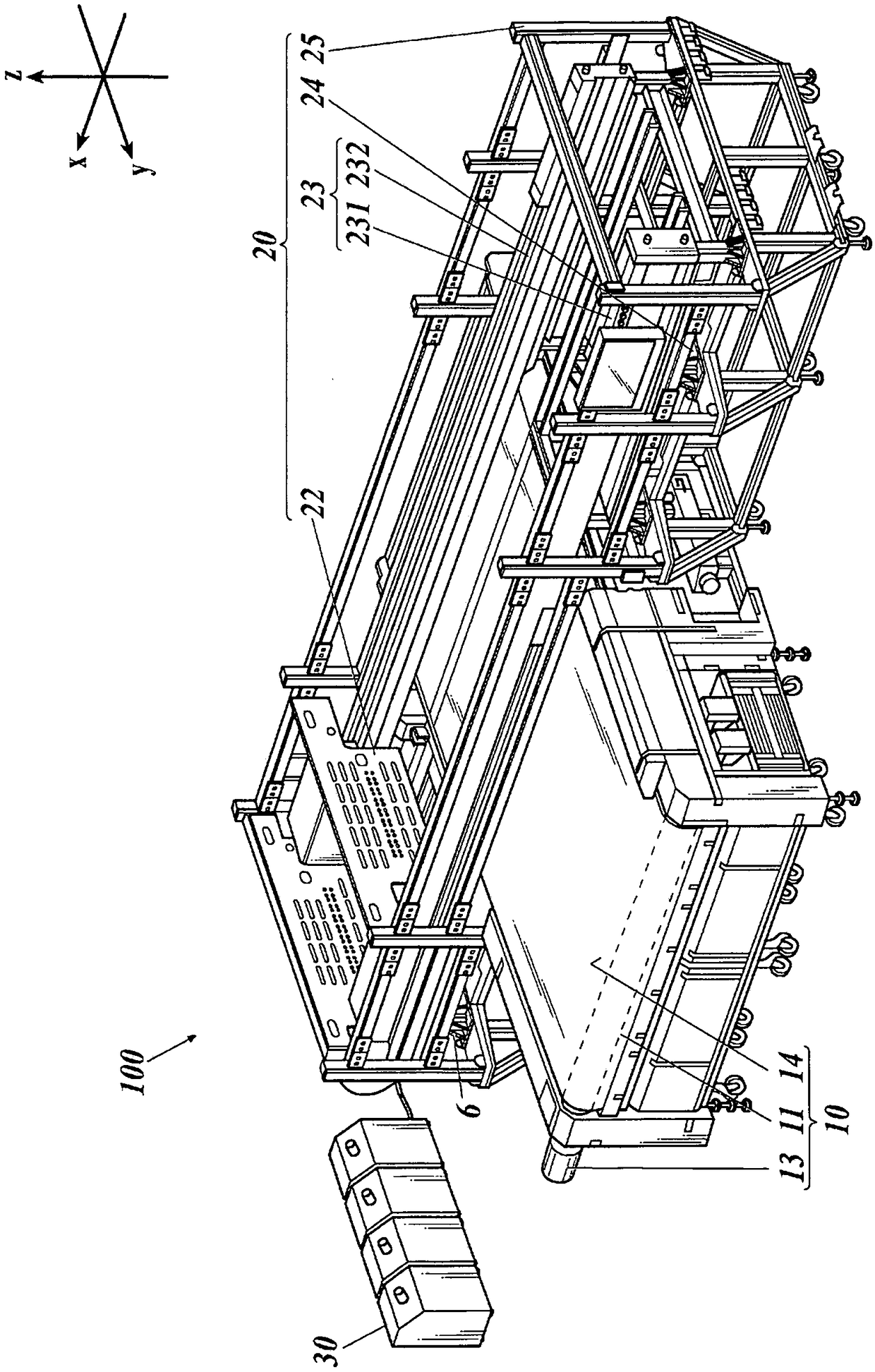
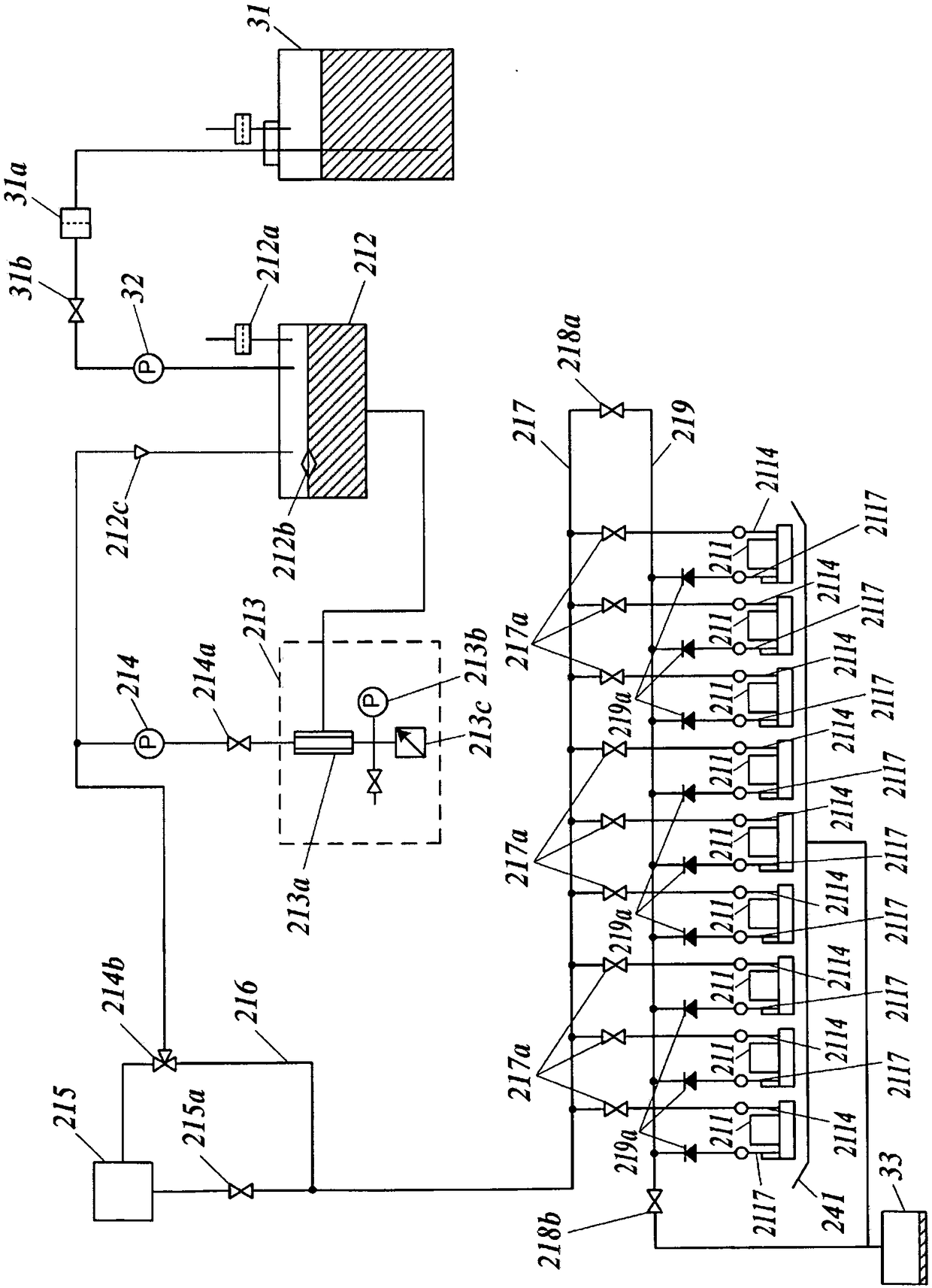
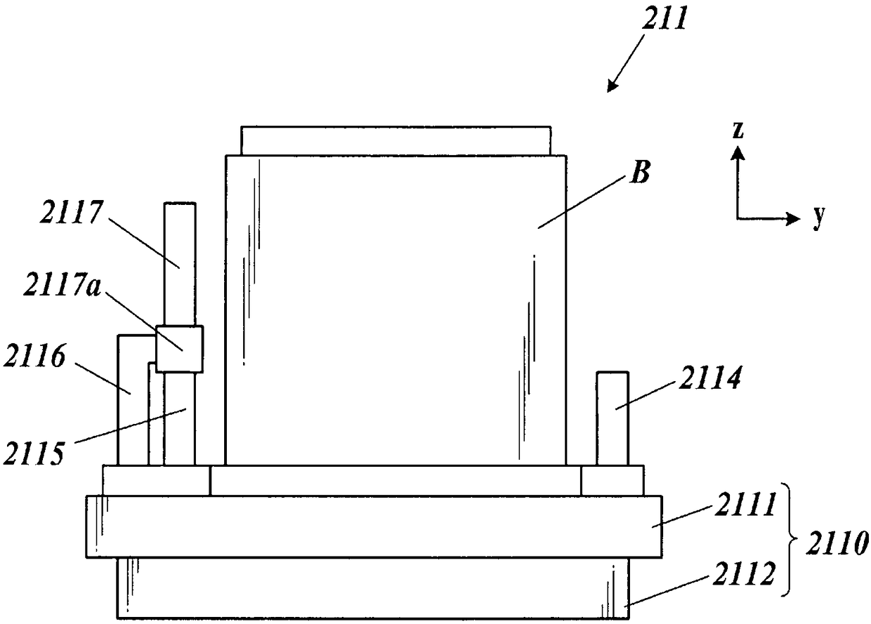
Provided is an inkjet recording apparatus for easily and quickly removing an air bubble in an ink flow path, and an air bubble removal method. The inkjet recording apparatus is provided with: a recording head; a first discharge section (2115); a second discharge section (2116); a feeding unit; and a control unit. In the ink flow path of the recording head, there are disposed a shared ink chamber (2111) which has an ink flow inlet (2111d), a filter (2118) that filters the ink, a first flow outlet (2111e) to the first discharge section for ink on an upstream side of the filter, a second flow outlet (2111f) to the second discharge section for filtered ink on a downstream side, and a connecting hole (2111c) to a nozzle for the downstream side ink. The control unit determines an ink feeding amount by the feeding unit so that a minimum flow rate of the ink on the upstream side and a minimum flow rate of the ink on the downstream side are simultaneously equal to or more than a predetermined reference rate.

Description

Technical field [0001] The present invention relates to an inkjet recording device and a method for removing bubbles. Background technique [0002] Conventionally, there has been an inkjet recording apparatus that performs image recording and three-dimensional structure formation by ejecting ink droplets and hitting them on a recording medium in a desired pattern. In this inkjet recording apparatus, a technique is used in which ink is pressurized in a suitable pressure change pattern to eject ink droplets from nozzles at a desired amount and speed. [0003] At this time, if foreign matter such as dust and dust is mixed in the ink, the quality of the recorded image and the formed structure will be reduced. Therefore, in the inkjet head, before the ink supplied from the ink tank reaches the nozzles, for example, a filter that removes these foreign substances is provided in a common flow path or a common ink chamber immediately before the ink is distributed to each nozzle. [0004] On...

Claims


Application Information

Patent Timeline
IPC IPC(8): B41J2/19B41J2/01B41J2/175
CPCB41J2/01B41J2/175B41J2/19
Inventor 山崎健秋田宏森川修三觜拓村松靖彦原见武史青木哲志
Owner KONICA MINOLTA INC
Learn More