
Gas supply small valve protection device of pneumatic valve

A technology for valve protection and pneumatic valves, applied to valve devices, valve operating/release devices, cocks including cut-off devices, etc., can solve the problems of high material consumption, poor isolation effect, and no suitable chain for binding straps, etc., to achieve Effect of avoiding economic loss, wide application prospect and application value

Inactive Publication Date: 2018-07-17
CNNC FUJIAN FUQING NUCLEAR POWER
View PDF4 Cites 0 Cited by
  • Summary
  • Abstract
  • Description
  • Claims
  • Application Information

AI Technical Summary

Problems solved by technology

The temporary binding method of binding tape has the following disadvantages: the temporary binding of the small gas supply valve with the binding tape is not applicable in the radiation control area environment of the nuclear power plant, and there is a problem of generating radioactive waste; when the state of the small gas supply valve needs to be changed frequently, each time It is necessary to cut the binding strap first and then bind it again after the operation. The operation is complicated and the binding strap material consumption is large because the binding strap cannot be reused; when it is necessary to isolate and lock the small air supply valve of the pneumatic valve, there is no suitable chain for locking and isolation lead to poor isolation

Method used


Image

  • Gas supply small valve protection device of pneumatic valve
  • Gas supply small valve protection device of pneumatic valve

Examples


Embodiment Construction

[0018] A small air supply valve protection device for a pneumatic valve according to the present invention will be further described in detail below in conjunction with the accompanying drawings and specific embodiments.

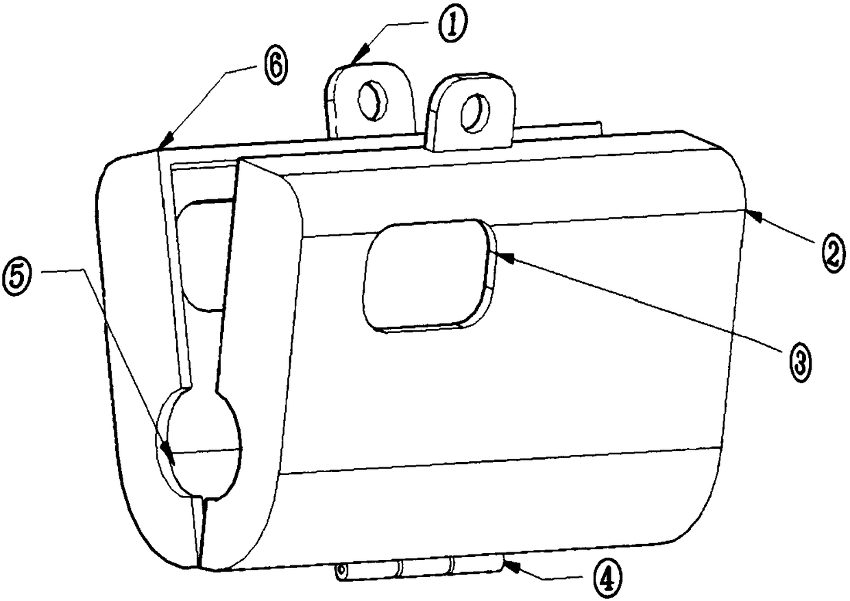
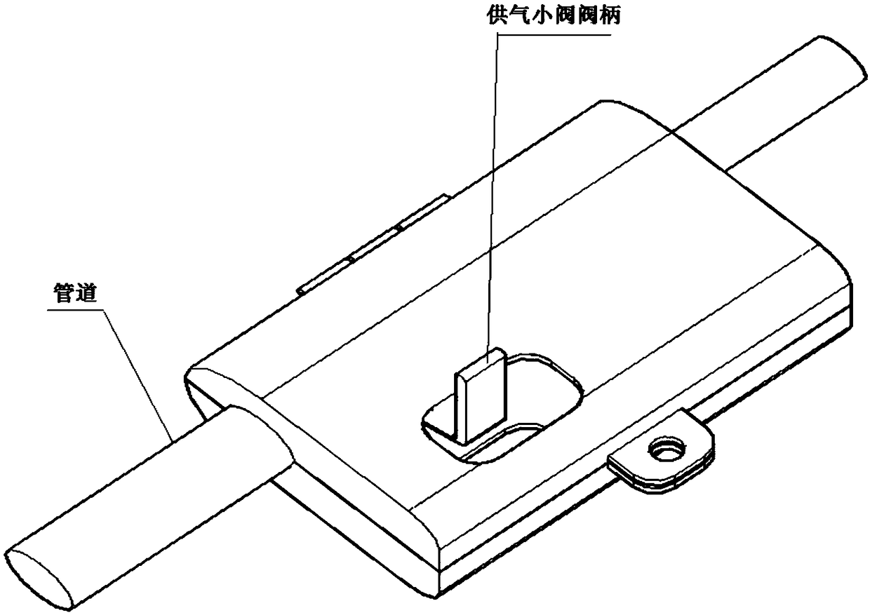
[0019] Such as figure 1 with figure 2 As shown, a small air supply valve protection device for a pneumatic valve includes half body A2 and half body B6, the lower ends of half body A2 and half body B6 are connected by lock hinge 4; the upper ends of half body A2 and half body B6 A lock hole 1 is respectively provided at the same position for locking; a pipe hole 5 is respectively provided at the same position on the left and right sides of the half body A2 and the half body B6, and when the half body A2 and the half body B6 are closed, the pipe Hole 5 fits with the pipeline of the small air supply valve; valve handle hole 3 is respectively provided at the same position on the front and rear sides of half body A2 and half body B6, and the valve handle for t...


PUM

PropertyMeasurementUnit
Sizeaaaaaaaaaa

Abstract

The invention relates to a gas supply small valve protection device of a pneumatic valve. The gas supply small valve protection device comprises a half body A and a half body B. The lower end of the half body A and the lower end of the half body B are connected through a lock hinge. Each of the same positions of the upper ends of the half body A and the half body B is provided with a lock hole forlocking. Pipeline holes are formed in the same positions of the left side and the right side of the half body A and the half body B correspondingly. When the half body A and the half body B are closed, the pipeline holes coincide with a pipeline of a gas supply small valve. Valve handle holes are formed in the same positions of the front side and the rear side of the half body A and the half bodyB correspondingly for a valve handle of the gas supply small valve to stretch out. After the gas supply small valve protection device is used, mistaken touch preventing protection can be achieved forthe gas supply small valve; the situation that the gas supply small valve handle is touched mistakenly, the state of the pneumatic valve is changed, and the unit transient state or shutdown outage event is caused, economic losses caused by the shutdown outage due to the reason can be avoided, and powerful guarantee is provided for safe and stable running of a unit.

Description

technical field [0001] The invention belongs to the field of pneumatic valve protection, in particular to a small air supply valve protection device for a pneumatic valve. Background technique [0002] The present invention mainly provides physical protection for small air supply valves using pneumatic valves in power plants and related industries in the open state or closed state, preventing unexpected changes in the state of pneumatic valves caused by personnel accidentally touching the small air supply valves during on-site work, and ultimately affecting the power plant Transient state of operating equipment in related industries, which will lead to unplanned outage events or accidents in generator sets or production lines in related industries. After the design team has continuously improved the structure and specifications of the protection device according to the actual situation on site, it will be suitable for effective physical protection of ball valves of various s...

Claims


Application Information

Patent Timeline
IPC IPC(8): F16K31/12F16K5/06F16K31/60F16K27/06
CPCF16K31/12F16K5/06F16K27/067F16K31/60
Inventor 王祥刘延超程志远於豪周福建
Owner CNNC FUJIAN FUQING NUCLEAR POWER
Learn More